Service Manual
Page 2
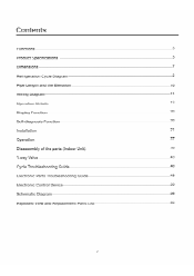
Functions Product Specifications Refrigeration Cycle Diagram Pipe Length and tha Flevation 10 iring uiagram Operation Details Display Function noels Function ns a a ion Operation Disassembly of the parts (Indoor Unit) -way valve 43 Cycle Troubleshooting Guide Electronic Parts Troubleshooting Guide ectronic Control Device e AO Exploded View and Replacement Parts List 2
Functions Product Specifications Refrigeration Cycle Diagram Pipe Length and tha Flevation 10 iring uiagram Operation Details Display Function noels Function ns a a ion Operation Disassembly of the parts (Indoor Unit) -way valve 43 Cycle Troubleshooting Guide Electronic Parts Troubleshooting Guide ectronic Control Device e AO Exploded View and Replacement Parts List 2

Service Manual
Page 21
.... • Do not place animals and plants in excessive noise and vibration, and maybe also classed as possible, allowing a minimum of Indoor, Outdoor unit Installation Parts Provided 1. Installation Read completely. More than 30cm(12") More than 2.3m(7.5ft) I More than 12cm(4.8") More than 30cm(12") ZL\ CAUTION Install the indoor unit...
.... • Do not place animals and plants in excessive noise and vibration, and maybe also classed as possible, allowing a minimum of Indoor, Outdoor unit Installation Parts Provided 1. Installation Read completely. More than 30cm(12") More than 2.3m(7.5ft) I More than 12cm(4.8") More than 30cm(12") ZL\ CAUTION Install the indoor unit...
Service Manual
Page 24
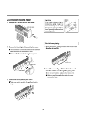
... hose 2. For left . Lower panel - 24 - Remove the 2 screws of rear left rear piping 1. Right side panel CAUTION When install, make sure that the remaining parts must be disconnected by pulling it while pressing the connectors hook. ■ Remove the 1 screw for easy connection later. Route the indoor tubing and the...
... hose 2. For left . Lower panel - 24 - Remove the 2 screws of rear left rear piping 1. Right side panel CAUTION When install, make sure that the remaining parts must be disconnected by pulling it while pressing the connectors hook. ■ Remove the 1 screw for easy connection later. Route the indoor tubing and the...
Service Manual
Page 28
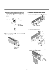
... hole ■ Refix the front right side panel to the original position. 4 Wrap with vinyl tape(wide) Lower panel • Connect display conductor. 8. Reinstall the parts to the original position. ■ Refix the lower panel to the original position with cloth tape over the range within which they fit into the...
... hole ■ Refix the front right side panel to the original position. 4 Wrap with vinyl tape(wide) Lower panel • Connect display conductor. 8. Reinstall the parts to the original position. ■ Refix the lower panel to the original position with cloth tape over the range within which they fit into the...
Service Manual
Page 33
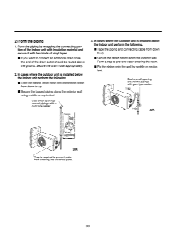
... indoor unit with insulation material and secure it with two kinds of vinyl tapes. • If you want to prevent water from entering into electrical parts. - 33 - Form a trap to up . ■ Secure the taped piping along the exterior wall using saddle or equivalent. Trap 1115„, $114111 Trap 3 30K IPipings...
... indoor unit with insulation material and secure it with two kinds of vinyl tapes. • If you want to prevent water from entering into electrical parts. - 33 - Form a trap to up . ■ Secure the taped piping along the exterior wall using saddle or equivalent. Trap 1115„, $114111 Trap 3 30K IPipings...
Service Manual
Page 34
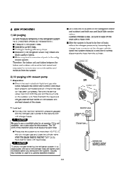
.... ■ Cooling(or heating) efficiency drops. ■ Moisture in the refrigerant circuit may freeze and block capillary tubing. ■ Water may lead to corrosion of parts in a liquid state, the top of the cylinder must be free of the tubing(both indoor and outdoor) and both liquid and gas side tubes...
.... ■ Cooling(or heating) efficiency drops. ■ Moisture in the refrigerant circuit may freeze and block capillary tubing. ■ Water may lead to corrosion of parts in a liquid state, the top of the cylinder must be free of the tubing(both indoor and outdoor) and both liquid and gas side tubes...
Service Manual
Page 39
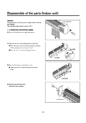
To remove the Grille from power supply before making any checks. O Remove the 2 screws of the parts (Indoor unit) Warning : Disconnect the unit from the Chassis. Be sure the power switch is set to drop. Right side panel O Remove the front right ...
To remove the Grille from power supply before making any checks. O Remove the 2 screws of the parts (Indoor unit) Warning : Disconnect the unit from the Chassis. Be sure the power switch is set to drop. Right side panel O Remove the front right ...
Service Manual
Page 49
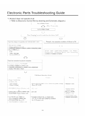
... Misers-No. 2, n oor unit (DC +4.5V over)-and Soldering condition, No-5-(Outdoor=unit) -•-Replace IC0l D (Outdoor unit) -.-Replace IC02D Otrtdoor-urrit)- ( n our unit)- -Replaeefaulty parts- - 49 - Voltagc of mom is Cheek each ludd(Irrduur/Oulduur Fdll MU Ur. DC +5V - 1- Check the connection housing for co • Connector related-to...
... Misers-No. 2, n oor unit (DC +4.5V over)-and Soldering condition, No-5-(Outdoor=unit) -•-Replace IC0l D (Outdoor unit) -.-Replace IC02D Otrtdoor-urrit)- ( n our unit)- -Replaeefaulty parts- - 49 - Voltagc of mom is Cheek each ludd(Irrduur/Oulduur Fdll MU Ur. DC +5V - 1- Check the connection housing for co • Connector related-to...
Service Manual
Page 50
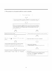
...-steppedIndoor Fan is driven by a low speed At this point the wind-speed-is-not-Gentroired by force.) ause nv the remote controner Cause&brether-parts-exeept-the-remdte-eantroller- 2) When the mark( Is &played in LCD screen. R17(212k) - When operated in the, Sleeping,Modethe=wind speed is w speed by...
...-steppedIndoor Fan is driven by a low speed At this point the wind-speed-is-not-Gentroired by force.) ause nv the remote controner Cause&brether-parts-exeept-the-remdte-eantroller- 2) When the mark( Is &played in LCD screen. R17(212k) - When operated in the, Sleeping,Modethe=wind speed is w speed by...
Service Manual
Page 53
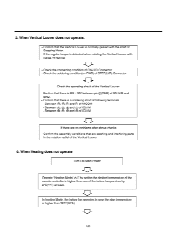
... of the Vertical Louver • Confirm that there is DC +12V between pinT(RED) of CN-U/D and GND. • Confirm that are catching and interfering parts in case the pipe temperature is a soldering short at least.
... of the Vertical Louver • Confirm that there is DC +12V between pinT(RED) of CN-U/D and GND. • Confirm that are catching and interfering parts in case the pipe temperature is a soldering short at least.


