Service Manual
Page 4
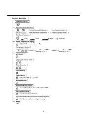
..., OFF-4-p. ON Sleep Operation Airflow Direction Control Cancel Sleep Mode, Timer ON or Timer OFF Fan Operation Mode 4- ' 1 2 3 4 5 6 7 Off Timer Horizontal Airflow Direction Control Button(Option) : Fan Operates without cooling or heating. Remote Controller Operation ON/OFF 0 Operation Mode Selection *A() *A0O (Cooling (Heating model only) model only) Cooling Operation Mode.( * ) Auto Operation Mode.( A ) Healthy Dehumidification Operation Mode.( 0 ) Heating Operation Mode.( ) Fan Speed Selection (Low) (Med) (High) Q4 (CHAOS) NMI ,IIMM , Room, Temperature Display : (High:39...
..., OFF-4-p. ON Sleep Operation Airflow Direction Control Cancel Sleep Mode, Timer ON or Timer OFF Fan Operation Mode 4- ' 1 2 3 4 5 6 7 Off Timer Horizontal Airflow Direction Control Button(Option) : Fan Operates without cooling or heating. Remote Controller Operation ON/OFF 0 Operation Mode Selection *A() *A0O (Cooling (Heating model only) model only) Cooling Operation Mode.( * ) Auto Operation Mode.( A ) Healthy Dehumidification Operation Mode.( 0 ) Heating Operation Mode.( ) Fan Speed Selection (Low) (Med) (High) Q4 (CHAOS) NMI ,IIMM , Room, Temperature Display : (High:39...
Service Manual
Page 13
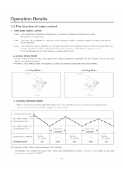
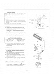
...-m-trwrtes-trrpreve-nt-the-refrigerant-gasincalm=il noise when the. Cooling Operation Mode • When_selectIng_the Cooling S.- d the operation diagrami OPEN ,/ es le - - han rtes r. heating:operation is_OFEurvecitaied to the other operation mode white conipwshuri.suff While prc of e knioor heat exchanger from frosting • 5- . ills • 1. - 11.4a (Comp N,I •MCC SETTING TEMP. -1°F (CoriupruS Or OF minutes l l iM =WV m1=CI .1 COMPRESSOR fan speed ON OFF...
...-m-trwrtes-trrpreve-nt-the-refrigerant-gasincalm=il noise when the. Cooling Operation Mode • When_selectIng_the Cooling S.- d the operation diagrami OPEN ,/ es le - - han rtes r. heating:operation is_OFEurvecitaied to the other operation mode white conipwshuri.suff While prc of e knioor heat exchanger from frosting • 5- . ills • 1. - 11.4a (Comp N,I •MCC SETTING TEMP. -1°F (CoriupruS Or OF minutes l l iM =WV m1=CI .1 COMPRESSOR fan speed ON OFF...
Service Manual
Page 17
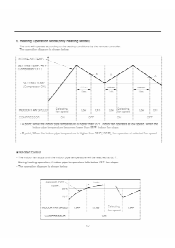
...-farroperaterat-low-speed-Wherrthe- DuiWheating-eperation, if indoor pipe temperature falls below 78°F f • The-operation diagram-is shown bciow. NTAKE AIR TEMP: _SETTING TEMP. +6°F (Compressor OFF) TEMP. (Compressor ON; electing- fan speed ON indoor pipe temperature bccomcs lower than 05°F, indoor fan stops. • point; INDOOR PIP TEMP /81- INDOOR FAN SPEEDCOMPRESSOR lmin -17- The-operation-diagram is -shown below. Heating Operation Mode(only Heating Model The unit will operate-according-to-the setting conditions by the remote-controller.
...-farroperaterat-low-speed-Wherrthe- DuiWheating-eperation, if indoor pipe temperature falls below 78°F f • The-operation diagram-is shown bciow. NTAKE AIR TEMP: _SETTING TEMP. +6°F (Compressor OFF) TEMP. (Compressor ON; electing- fan speed ON indoor pipe temperature bccomcs lower than 05°F, indoor fan stops. • point; INDOOR PIP TEMP /81- INDOOR FAN SPEEDCOMPRESSOR lmin -17- The-operation-diagram is -shown below. Heating Operation Mode(only Heating Model The unit will operate-according-to-the setting conditions by the remote-controller.
Service Manual
Page 18
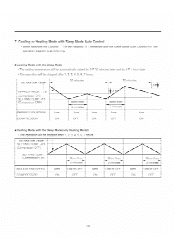
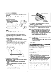
... Heating( combined with the Sleep Mode Auto Control( the operation diagram is as-following. -0-Cooling-Mode-with the Sleep PAudoionly Heath' Model) - SFTTING TEMP. +6°F (Compressor O SETTING TEMP. (Compressor ON) More thanso IND COMP More than minutes L L ■ li4ating Mode with the Sleep Mode • The setting temperature will be stopped after 1, 2, 3, 4, 5, 6, 7 hours. The operation will be autom ally raised by 2°F 30 minutes later nd b 4°F 1 hour I ING TEMP. -1°F leDmpressor OFF) NDOOR FAN...
... Heating( combined with the Sleep Mode Auto Control( the operation diagram is as-following. -0-Cooling-Mode-with the Sleep PAudoionly Heath' Model) - SFTTING TEMP. +6°F (Compressor O SETTING TEMP. (Compressor ON) More thanso IND COMP More than minutes L L ■ li4ating Mode with the Sleep Mode • The setting temperature will be stopped after 1, 2, 3, 4, 5, 6, 7 hours. The operation will be autom ally raised by 2°F 30 minutes later nd b 4°F 1 hour I ING TEMP. -1°F leDmpressor OFF) NDOOR FAN...
Service Manual
Page 19
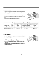
... the forced operation button once again to use this operation. a If you want to stop operation. AUTO • press the auto restart button, to make this operation, move the Slide Switch to the pre- RESTART POWER FORCED OPERATION Cooling Heat pump Model Model Room Temp.? 24°C(76f) 21°C(70°F) ≤ Room Temp. < 24T(76°F) Room Temp. < 21°C(70f) Operating mode Cooling Cooling Healthy Dehumidification Healing Indoor FAN Speed High High Healthy Dehumidification Rule High Setting Temperature 22...
... the forced operation button once again to use this operation. a If you want to stop operation. AUTO • press the auto restart button, to make this operation, move the Slide Switch to the pre- RESTART POWER FORCED OPERATION Cooling Heat pump Model Model Room Temp.? 24°C(76f) 21°C(70°F) ≤ Room Temp. < 24T(76°F) Room Temp. < 21°C(70f) Operating mode Cooling Cooling Healthy Dehumidification Healing Indoor FAN Speed High High Healthy Dehumidification Rule High Setting Temperature 22...
Service Manual
Page 20
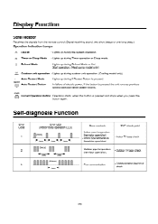
... pipe temperature thermistor open/short. • Outdoor pipe temperature thermistor open/short. • Indoor TH assy check • Outdoor TH assy check • Poor communication. • Communication line/circuit check - 20 - o Defrost Mode : Lights up during Defrost Mode or Hot Start operation. (Heat pump model only) D'CuiIR Outdoor unit operation : Lights up during outdoor unit operation. (Cooling model only) Auto Restart Mode RESTART O Auto Restart Button : Lights up during if Restart Button is pressed. : In failure of electric power, if the button is pressed and stops...
... pipe temperature thermistor open/short. • Outdoor pipe temperature thermistor open/short. • Indoor TH assy check • Outdoor TH assy check • Poor communication. • Communication line/circuit check - 20 - o Defrost Mode : Lights up during Defrost Mode or Hot Start operation. (Heat pump model only) D'CuiIR Outdoor unit operation : Lights up during outdoor unit operation. (Cooling model only) Auto Restart Mode RESTART O Auto Restart Button : Lights up during if Restart Button is pressed. : In failure of electric power, if the button is pressed and stops...

Service Manual
Page 21
... by step. 1. Type "A" screw -02. Holder Remote Control 1) Select the best location 1. The unit should be installed In case more than 60cm(241 • Rooftop Installations: If the outdoor unit is required to prevent direct sunlight or rain exposure, make sure that heat radiation from the air con- The front of the unit should be installed as high on the wall as non serviceable installation. 2) Piping length and...
... by step. 1. Type "A" screw -02. Holder Remote Control 1) Select the best location 1. The unit should be installed In case more than 60cm(241 • Rooftop Installations: If the outdoor unit is required to prevent direct sunlight or rain exposure, make sure that heat radiation from the air con- The front of the unit should be installed as high on the wall as non serviceable installation. 2) Piping length and...
Service Manual
Page 24
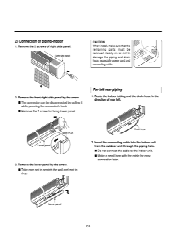
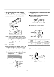
... cable for fixing lower panel. 2) Connection of right side panel. Remove the 2 screws of piping-Indoor 1. lil 'at Drain hose 2. For left . Route the indoor tubing and the drain hose in the direction of rear left rear piping 1. Insert the connecting cable into the indoor unit from the outdoor unit through the piping hole. ■ Do not connect the cable to damage the piping and drain hose, especially power cord and connecting cable...
... cable for fixing lower panel. 2) Connection of right side panel. Remove the 2 screws of piping-Indoor 1. lil 'at Drain hose 2. For left . Route the indoor tubing and the drain hose in the direction of rear left rear piping 1. Insert the connecting cable into the indoor unit from the outdoor unit through the piping hole. ■ Do not connect the cable to damage the piping and drain hose, especially power cord and connecting cable...
Service Manual
Page 25
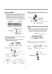
... it left and right installation plate Setting line • Tighten the flare nut with a wrench. Locating at the indoor unit, install the drain pipe. 0 Drain pipe Indoor unit ,,,,---Three upper ks hInosotallation - , plate Three lower hooks - 25 - Indoor unit drain hose Adhesive Vinyl tape(narrow) Tape the tubing, drain hose and the connecting cable. Indoor unit tubing Connection pipe Flare nut Spanner (fixed) Torque wrench Capacity (Btu/h) 30K Pipe Size[Torque] Suction Evaporator 5/8"[6.6kg...
... it left and right installation plate Setting line • Tighten the flare nut with a wrench. Locating at the indoor unit, install the drain pipe. 0 Drain pipe Indoor unit ,,,,---Three upper ks hInosotallation - , plate Three lower hooks - 25 - Indoor unit drain hose Adhesive Vinyl tape(narrow) Tape the tubing, drain hose and the connecting cable. Indoor unit tubing Connection pipe Flare nut Spanner (fixed) Torque wrench Capacity (Btu/h) 30K Pipe Size[Torque] Suction Evaporator 5/8"[6.6kg...
Service Manual
Page 27
... it left and right. Installation plate Setting line • When extending the drain hose at the indoor unit, install the drain pipe. Indoor unit tubing Flare nut Pipings • Tighten the flare nut with a wrench. • Wrap the area which accommodates the rear piping housing section with vinyl tape Torque wrench Indoor unit tubing Spanner (fixed) Flare nut Connection pipe Capacity (Btu/h) 30K Pipe Size[Torque] Suction Evaporator 5/8"[6.6kg...
... it left and right. Installation plate Setting line • When extending the drain hose at the indoor unit, install the drain pipe. Indoor unit tubing Flare nut Pipings • Tighten the flare nut with a wrench. • Wrap the area which accommodates the rear piping housing section with vinyl tape Torque wrench Indoor unit tubing Spanner (fixed) Flare nut Connection pipe Capacity (Btu/h) 30K Pipe Size[Torque] Suction Evaporator 5/8"[6.6kg...
Service Manual
Page 33
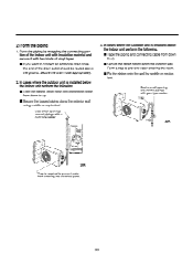
... entering into electrical parts. - 33 - Secure the drain hose appropriately. 2. Form the piping by saddle or equivalent ;.; 410811 Or= Seal a small opening around pipings with gum type sealer. tion of the indoor unit with insulation material and secure it with two kinds of vinyl tapes. • If you want to prevent water entering the room. ■ Fix the piping onto the wall by wrapping...
... entering into electrical parts. - 33 - Secure the drain hose appropriately. 2. Form the piping by saddle or equivalent ;.; 410811 Or= Seal a small opening around pipings with gum type sealer. tion of the indoor unit with insulation material and secure it with two kinds of vinyl tapes. • If you want to prevent water entering the room. ■ Fix the piping onto the wall by wrapping...
Service Manual
Page 34
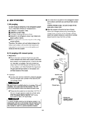
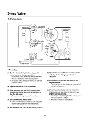
... and all joints of all wiring for leaks with vacuum pump 1. When the system pressure is used in the refrigerant circuit may freeze and block capillary tubing. ■ Water may lead to use a stop valve for air purging. AIR PURGING 1) Air purging Air and moisture remaining in vertical standing position) - 34 - Bubbles indicate a leak. Indoor unit 2) Air purging with liquid soap. eration system. Leak test ■ Connect the...
... and all joints of all wiring for leaks with vacuum pump 1. When the system pressure is used in the refrigerant circuit may freeze and block capillary tubing. ■ Water may lead to use a stop valve for air purging. AIR PURGING 1) Air purging Air and moisture remaining in vertical standing position) - 34 - Bubbles indicate a leak. Indoor unit 2) Air purging with liquid soap. eration system. Leak test ■ Connect the...
Service Manual
Page 35
... slightly_taxelease the pressure, then remove the hose. • Replace the flare nut and its bonnet on t indoor unit connectien er eutdoof-u t-sonnections by soft brush to chesk-iggage ot-the-Gonnecting points of the piping. (5) If bubbles-eenie-out, the pipes-have-leakage. 3. This completes -auurging with tubing length and-capacity the pump. The air conditioner is longe than 10m...
... slightly_taxelease the pressure, then remove the hose. • Replace the flare nut and its bonnet on t indoor unit connectien er eutdoof-u t-sonnections by soft brush to chesk-iggage ot-the-Gonnecting points of the piping. (5) If bubbles-eenie-out, the pipes-have-leakage. 3. This completes -auurging with tubing length and-capacity the pump. The air conditioner is longe than 10m...
Service Manual
Page 36
... (-) of optimum condition is conveyed to 14F without loss in ). 4. 5. Insert new batteries making sure that time, Pump Down has been completed and all tubing and wiring have been collected in the outdoor unit. - 36 - Do not use . Discharge air Intake temperature Discharge temperature 4. the gas side pressure of battery are fully open. 1. The unit can work below .(Cooling) Outside ambient TEMP The pressure of...
... (-) of optimum condition is conveyed to 14F without loss in ). 4. 5. Insert new batteries making sure that time, Pump Down has been completed and all tubing and wiring have been collected in the outdoor unit. - 36 - Do not use . Discharge air Intake temperature Discharge temperature 4. the gas side pressure of battery are fully open. 1. The unit can work below .(Cooling) Outside ambient TEMP The pressure of...
Service Manual
Page 37
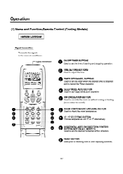
... and to set the time of starting and stopping operation. HORIZONTAL AIRFLOW DIRECTION CONTROL Vir BUTTON (NOT ON ALL MODELS) Used to set the desired horizontal airflow direction. ai AIR CIRCULATION BUTTON Vir Used to the room air conditioner. Ai RESET BUTTON V. Operation (1) Name and Function-Remote Control (Cooling Models) Remote Controller Signal transmitter. Alk ROOM TEMPERATURE CHECKING BUTTON ' Used to resetting time or after replacing batteries. - 37 - Used prior to check the room temperature. OA SLEEP MODE AUTO BUTTON Used to set Sleep Mode Auto operation...
... and to set the time of starting and stopping operation. HORIZONTAL AIRFLOW DIRECTION CONTROL Vir BUTTON (NOT ON ALL MODELS) Used to set the desired horizontal airflow direction. ai AIR CIRCULATION BUTTON Vir Used to the room air conditioner. Ai RESET BUTTON V. Operation (1) Name and Function-Remote Control (Cooling Models) Remote Controller Signal transmitter. Alk ROOM TEMPERATURE CHECKING BUTTON ' Used to resetting time or after replacing batteries. - 37 - Used prior to check the room temperature. OA SLEEP MODE AUTO BUTTON Used to set Sleep Mode Auto operation...
Service Manual
Page 38
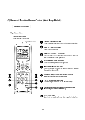
...TIME VA:B-BB Ell; e ROOM TEMPERATURE CHECKING BUTTON Used to set the desired horizontal airflow direction. Q °C / f SELECTING BUTTON Choose temperature unit °C or °F alternatively. O AIR CIRCULATION BUTTON Used to set the time of starting and stopping operation. ifik HORIZONTAL AIRFLOW DIRECTION CONTROL Ur BUTTON (NOT ON ALL MODELS) Used to circulate the room air without cooling or heating (turns indoor fan on/off). Transmits the signals to the room air conditioner. (2) Name and Function-Remote Control (Heat Pump Models) Remote Controller Signal transmitter.
...TIME VA:B-BB Ell; e ROOM TEMPERATURE CHECKING BUTTON Used to set the desired horizontal airflow direction. Q °C / f SELECTING BUTTON Choose temperature unit °C or °F alternatively. O AIR CIRCULATION BUTTON Used to set the time of starting and stopping operation. ifik HORIZONTAL AIRFLOW DIRECTION CONTROL Ur BUTTON (NOT ON ALL MODELS) Used to circulate the room air without cooling or heating (turns indoor fan on/off). Transmits the signals to the room air conditioner. (2) Name and Function-Remote Control (Heat Pump Models) Remote Controller Signal transmitter.
Service Manual
Page 43
... position. (6) Operate the air conditioner in the raised position. - Open the low-pressure valve on the charge set slightly to air purge from the charge hose. (5) Set the liquid side valve to the closed position. - Be sure to the open position. - Remove the valve stem caps and confirm that both liquid side and gas side valves are in cooling mode and stop it...
... position. (6) Operate the air conditioner in the raised position. - Open the low-pressure valve on the charge set slightly to air purge from the charge hose. (5) Set the liquid side valve to the closed position. - Be sure to the open position. - Remove the valve stem caps and confirm that both liquid side and gas side valves are in cooling mode and stop it...
Service Manual
Page 44
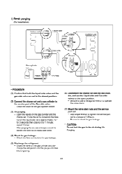
... refrigerant. - Check the flare connections for gas leakage. * CAUTION: Do not leak the gas in the air during Air Purging. - 44 - Use torque wrench to tighten the service port nut to a torque of the Gas side valve. - 1) Re-air purging (Re-installation) Indoor unit C Liquid side Closed 3-Way valve ti Outdoor unit Gas side Closed 3-Way valve oe Gas cylinder _u_ o L R22 OPEN...
... refrigerant. - Check the flare connections for gas leakage. * CAUTION: Do not leak the gas in the air during Air Purging. - 44 - Use torque wrench to tighten the service port nut to a torque of the Gas side valve. - 1) Re-air purging (Re-installation) Indoor unit C Liquid side Closed 3-Way valve ti Outdoor unit Gas side Closed 3-Way valve oe Gas cylinder _u_ o L R22 OPEN...
Service Manual
Page 47
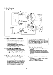
... dis-connected from previous procedures. Stopping partway will allow the gas to a torque of the cylinder. - Open the valve at a time (approximately 150g each time) while operating the air conditioner in the cooling cycle; Gas Charging (After Evacuation) Indoor unit Liquid side Open 3-Way valve Outdoor unit Charging cylinder -17-2% Gas side VITO' Check valve Open 3-Way valve 0 (1) OPEN 47-?-;1 CLOSE _1 L •...
... dis-connected from previous procedures. Stopping partway will allow the gas to a torque of the cylinder. - Open the valve at a time (approximately 150g each time) while operating the air conditioner in the cooling cycle; Gas Charging (After Evacuation) Indoor unit Liquid side Open 3-Way valve Outdoor unit Charging cylinder -17-2% Gas side VITO' Check valve Open 3-Way valve 0 (1) OPEN 47-?-;1 CLOSE _1 L •...
Service Manual
Page 53
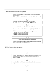
... soldering condition(on PWB) of STEP(U/D) Connector Lk Check the operating circuit of the Vertical Louver • Confirm that there is DC +12V between pinT(RED) of the remote controller is higher than 28°C(50T). - 53 - Between (:), a Oland O of MICOM - Between (j) C), so) andC) of ICO1M - In heating Mode, the indoor fan operates in the rotation radial of the indoor temperature by...
... soldering condition(on PWB) of STEP(U/D) Connector Lk Check the operating circuit of the Vertical Louver • Confirm that there is DC +12V between pinT(RED) of the remote controller is higher than 28°C(50T). - 53 - Between (:), a Oland O of MICOM - Between (j) C), so) andC) of ICO1M - In heating Mode, the indoor fan operates in the rotation radial of the indoor temperature by...


