

Service Manual
Page 15
Pull the connector. - 15 - Disassembly Hinge Cover. # 9 # 10 Remove the screws. # 11 Disassembly back cover. # 7 # 8 Pull base body to separate from set during pressing 2 letches. 1. Remove the screws. 2.
Pull the connector. - 15 - Disassembly Hinge Cover. # 9 # 10 Remove the screws. # 11 Disassembly back cover. # 7 # 8 Pull base body to separate from set during pressing 2 letches. 1. Remove the screws. 2.
Service Manual
Page 16
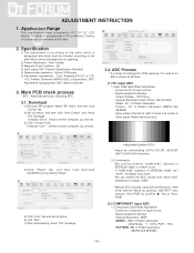
...(Refer below picture)]. 4) Click "Read" tab, and then load download file(XXXX.bin) by clicking "Read". 5) Click "Auto" tab and set as below 6) click "Run". 7) After downloading, check "OK" message. - Signal equipment displays Impress Resolution 480P MODEL : 212 in Pattern Generator...: 60 in Pattern Generator Pattern : 29 in Pattern Generator (MSPG-925 SERISE) - 16 - If display "Error", Check connect computer, jig, and set . 3.2. Specification 1) The adjustment is according to do ADC process at "AutoRGB". (2) COMPONENT input ADC 1) Component Gain/Offset Adjustment - ADC Process ...
...(Refer below picture)]. 4) Click "Read" tab, and then load download file(XXXX.bin) by clicking "Read". 5) Click "Auto" tab and set as below 6) click "Run". 7) After downloading, check "OK" message. - Signal equipment displays Impress Resolution 480P MODEL : 212 in Pattern Generator...: 60 in Pattern Generator Pattern : 29 in Pattern Generator (MSPG-925 SERISE) - 16 - If display "Error", Check connect computer, jig, and set . 3.2. Specification 1) The adjustment is according to do ADC process at "AutoRGB". (2) COMPONENT input ADC 1) Component Gain/Offset Adjustment - ADC Process ...

Service Manual
Page 17
... in a page "0xB4". 3.3. Input signal : (1024 x 768 @ 60Hz), Full white 255/255 gray level (100 IRE, Model : 60, Pattern : 4 at MSPG925L) - Set CSM : 9300k - Input signal : (1024 x 768 @ 60Hz) Full white 255/255 gray level (100 IRE, Model : 60, Pattern : 4 at MSPG925L) - Confirm color ... "0xAA", we adjust once more. - Confirm whether x = 0.313±0.03, y = 0.329±0.03 or not. - Confirm color coordinate of component (1) Set Input to RGB. - Other quality - - Adjust by pressing AUTO Key after varying the Clock & the Phase 4.6. If "0x8D,0x8E" address of RGB * Check ...
... in a page "0xB4". 3.3. Input signal : (1024 x 768 @ 60Hz), Full white 255/255 gray level (100 IRE, Model : 60, Pattern : 4 at MSPG925L) - Set CSM : 9300k - Input signal : (1024 x 768 @ 60Hz) Full white 255/255 gray level (100 IRE, Model : 60, Pattern : 4 at MSPG925L) - Confirm color ... "0xAA", we adjust once more. - Confirm whether x = 0.313±0.03, y = 0.329±0.03 or not. - Confirm color coordinate of component (1) Set Input to RGB. - Other quality - - Adjust by pressing AUTO Key after varying the Clock & the Phase 4.6. If "0x8D,0x8E" address of RGB * Check ...

Service Manual
Page 18
...pressing IN-STOP key by SVC Remote controller. Check if Power LED Color and Power Consumption operate as standard. (1) Set Input to RGB and connect D-sub cable to set. (2) Measurement Condition : 230V@ 50Hz (Analog) (3) Confirm DPM operation at the state of 0xBC~0xBE page. ...18 - Select input DVI model 112(1440*900@60hz), 64 Gray Scale pattern and whether picture is different among the sets. 4.10. (5) DVI *M198WA - DPM operation confirmation - HDCP SETTING (High-Bandwidth Digital Contents Protection) 1) Connect D-sub Signal Cable to Product spec). (1) M198WA EDID DATA 1) ANALOG DATA...
...pressing IN-STOP key by SVC Remote controller. Check if Power LED Color and Power Consumption operate as standard. (1) Set Input to RGB and connect D-sub cable to set. (2) Measurement Condition : 230V@ 50Hz (Analog) (3) Confirm DPM operation at the state of 0xBC~0xBE page. ...18 - Select input DVI model 112(1440*900@60hz), 64 Gray Scale pattern and whether picture is different among the sets. 4.10. (5) DVI *M198WA - DPM operation confirmation - HDCP SETTING (High-Bandwidth Digital Contents Protection) 1) Connect D-sub Signal Cable to Product spec). (1) M198WA EDID DATA 1) ANALOG DATA...

Service Manual
Page 19
... or not when between power board's ac block and GND is impacked on 1.5kV(dc) or 2.2kV(dc) for one second. 4.12 Option data setting (SVC OSD setting) (1) Tool Option *M198WA-BMH- 4.11. Internal pressure - Tool Option 7809 Resolution Module TV VIDEO COMPONENT PC-RGB DVI HDMI M198WA-BTH 1 0 1 1 1 1 1 0 REMARK WXGA+ *M208WA...
... or not when between power board's ac block and GND is impacked on 1.5kV(dc) or 2.2kV(dc) for one second. 4.12 Option data setting (SVC OSD setting) (1) Tool Option *M198WA-BMH- 4.11. Internal pressure - Tool Option 7809 Resolution Module TV VIDEO COMPONENT PC-RGB DVI HDMI M198WA-BTH 1 0 1 1 1 1 1 0 REMARK WXGA+ *M208WA...
Service Manual
Page 20
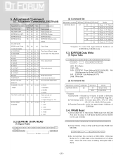
...E2PROM Slave Address(A0,A2,A4,A6,A8), Not 00h(Reserved by BufferToEEPROM) ADL : E2PROM Sub Address(00~FF) Data : Write data (2) Command Set Adjustment contents CMD(hex) EEPROM WRITE E8 ADH(hex) 94 84+n Details 16-Byte Write n-byte Write * Purpose 1) EDID write : 16-byte ... TV" AUTO_INPUT F4 00 0,1,2,4 0 : TV CHANGE 1 : AV1 2 : AV2 3 : Component 4 : RGB 5 : DVI 5.2 EEPROM DATA READ (1) Signal Table Delay 100ms 128 Bytes (2) Command Set Adjustment contents CMD(hex) ADH(hex) ADL(hex) Details EEPROM READ E7 A0 0 0-Page 0~7F Read 80 0-Page 80~FF Read A2 0 1-Page 0~7F Read...
...E2PROM Slave Address(A0,A2,A4,A6,A8), Not 00h(Reserved by BufferToEEPROM) ADL : E2PROM Sub Address(00~FF) Data : Write data (2) Command Set Adjustment contents CMD(hex) EEPROM WRITE E8 ADH(hex) 94 84+n Details 16-Byte Write n-byte Write * Purpose 1) EDID write : 16-byte ... TV" AUTO_INPUT F4 00 0,1,2,4 0 : TV CHANGE 1 : AV1 2 : AV2 3 : Component 4 : RGB 5 : DVI 5.2 EEPROM DATA READ (1) Signal Table Delay 100ms 128 Bytes (2) Command Set Adjustment contents CMD(hex) ADH(hex) ADL(hex) Details EEPROM READ E7 A0 0 0-Page 0~7F Read 80 0-Page 80~FF Read A2 0 1-Page 0~7F Read...

Service Manual
Page 22
... History ETC 7810 S.Am 1 0 1 Description of operation - Area Option : Adjust Area Option (S.Am : South America) - 2HR OFF : If no key input is made for 2 hours, Sets the Power off - ETC Video Signal Generator Control Line IBM Compatible PC 15 10 5 PARALLEL PORT Not used RS232C PARALLEL OFF ON 5V C F VGS A MONITOR...
... History ETC 7810 S.Am 1 0 1 Description of operation - Area Option : Adjust Area Option (S.Am : South America) - 2HR OFF : If no key input is made for 2 hours, Sets the Power off - ETC Video Signal Generator Control Line IBM Compatible PC 15 10 5 PARALLEL PORT Not used RS232C PARALLEL OFF ON 5V C F VGS A MONITOR...


