
Owners Manual
Page 3
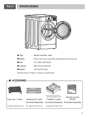
... Separately Purchased Separately See page 26 for how to change without manafaturers notice. See page 14 for how to the rating label regarding detailed information. Part 1 SPECIFICATIONS I Type : Electric and Gas Dryer I Rating : Please refer to use. 3
... Separately Purchased Separately See page 26 for how to change without manafaturers notice. See page 14 for how to the rating label regarding detailed information. Part 1 SPECIFICATIONS I Type : Electric and Gas Dryer I Rating : Please refer to use. 3
Owners Manual
Page 4
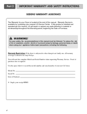
...to prevent property damage, personal injury, or death when using your new LG dryer. Serial No. Date of purchase date is effective for your Dryer is available by contacting your receipt HERE. 4 Part 2 IMPORTANT WARRANTY AND SAFETY INSTRUCTIONS SEEKING WARRANTY ASSISTANCE The Warranty for only... 90 days. WARNING! Model No. If this product is installed and operated per this manual, LG will need the complete Model and Serial Number...
...to prevent property damage, personal injury, or death when using your new LG dryer. Serial No. Date of purchase date is effective for your Dryer is available by contacting your receipt HERE. 4 Part 2 IMPORTANT WARRANTY AND SAFETY INSTRUCTIONS SEEKING WARRANTY ASSISTANCE The Warranty for only... 90 days. WARNING! Model No. If this product is installed and operated per this manual, LG will need the complete Model and Serial Number...
Owners Manual
Page 5
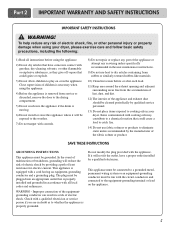
...appliance must be plugged into the appliance if the drum is equipped with a cord having an equipment-grounding conductor and a grounding plug. Part 2 IMPORTANT WARRANTY AND SAFETY INSTRUCTIONS IMPORTANT SAFETY INSTRUCTIONS ! Items contaminated with all instructions before or after each load. 11) Keep area around...malfunction or breakdown, grounding will not fit the outlet, have come into contact with controls. 8) Do not repair or replace any part of the appliance or attempt any risk of electric shock, fire, or other flammable or explosive substances, as to whether the appliance...
...appliance must be plugged into the appliance if the drum is equipped with a cord having an equipment-grounding conductor and a grounding plug. Part 2 IMPORTANT WARRANTY AND SAFETY INSTRUCTIONS IMPORTANT SAFETY INSTRUCTIONS ! Items contaminated with all instructions before or after each load. 11) Keep area around...malfunction or breakdown, grounding will not fit the outlet, have come into contact with controls. 8) Do not repair or replace any part of the appliance or attempt any risk of electric shock, fire, or other flammable or explosive substances, as to whether the appliance...

Owners Manual
Page 6
... by your building. • Clear the room, building or area of these substances can result in the area surrounding this appliance. ! Exposure to such substances. Part 2 IMPORTANT WARRANTY AND SAFETY INSTRUCTIONS !
... by your building. • Clear the room, building or area of these substances can result in the area surrounding this appliance. ! Exposure to such substances. Part 2 IMPORTANT WARRANTY AND SAFETY INSTRUCTIONS !
Owners Manual
Page 7
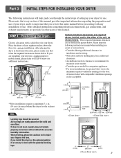
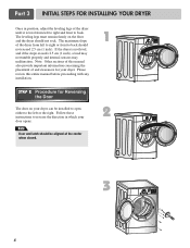
... require a minimum 5 1/2 in the desired location, please make sure that you through the initial steps of setting up your dryer in other parts of your dryer. ventilation hole ventilation hole 30.1 76.5 7 Please note that every section of this manual provides important information regarding the preparation...dryer on the solid and even floor. Choose a location with a solid floor for the exhaust vent with any installation or use . Part 3 INITIAL STEPS FOR INSTALLING YOUR DRYER The following instructions in mind when installing in the picture below . Place the dryer at least ...
... require a minimum 5 1/2 in the desired location, please make sure that you through the initial steps of setting up your dryer in other parts of your dryer. ventilation hole ventilation hole 30.1 76.5 7 Please note that every section of this manual provides important information regarding the preparation...dryer on the solid and even floor. Choose a location with a solid floor for the exhaust vent with any installation or use . Part 3 INITIAL STEPS FOR INSTALLING YOUR DRYER The following instructions in mind when installing in the picture below . Place the dryer at least ...
Owners Manual
Page 8
... sensors may malfunction. Follow these instructions to the left or the right. If the dryer is level from left to right or front to back. Part 3 INITIAL STEPS FOR INSTALLING YOUR DRYER Once in which your dryer. The leveling legs must remain firmly on your dryer can be aligned at the...
... sensors may malfunction. Follow these instructions to the left or the right. If the dryer is level from left to right or front to back. Part 3 INITIAL STEPS FOR INSTALLING YOUR DRYER Once in which your dryer. The leveling legs must remain firmly on your dryer can be aligned at the...
Owners Manual
Page 9
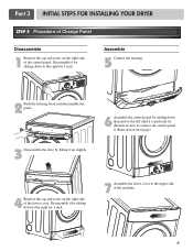
.... 4 Remove the cap and screw on the right side of the control panel. Disassemble it by sliding down to the upper side of the machine. 9 Part 3 INITIAL STEPS FOR INSTALLING YOUR DRYER STEP 3 Procedure of Change Panel Disassemble 1 Remove the cap and screw on the right side of the lower cover...
.... 4 Remove the cap and screw on the right side of the control panel. Disassemble it by sliding down to the upper side of the machine. 9 Part 3 INITIAL STEPS FOR INSTALLING YOUR DRYER STEP 3 Procedure of Change Panel Disassemble 1 Remove the cap and screw on the right side of the lower cover...
Owners Manual
Page 10
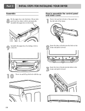
Ill one hole gets fixed, the others will do automatically. Part 3 INITIAL STEPS FOR INSTALLING YOUR DRYER Assemble 8 Fix the upper deco into the left side of the frame. 9 Assemble the upper deco by sliding it ...
Ill one hole gets fixed, the others will do automatically. Part 3 INITIAL STEPS FOR INSTALLING YOUR DRYER Assemble 8 Fix the upper deco into the left side of the frame. 9 Assemble the upper deco by sliding it ...
Owners Manual
Page 11
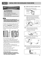
... THE DRYER CORRECTLY WILL VOID THE DRYER'S WARRANTY. 3-1. Reconnect the duct to the blower housing and attach the duct to the base.(Duct is a SVC part) • Do not use plastic or thin foil duct. • Failure to the outdoors. Please follow these instructions can result in this dryer • The... ducts before installing this dryer Note Vent end will face to manual section on Gas Dryers) , , the order of work. 2-2. Remove screw and exhaust duct. 2-1. Part 3 INITIAL STEPS FOR INSTALLING YOUR DRYER STEP 3 Connecting the Exhaust and Venting System. !
... THE DRYER CORRECTLY WILL VOID THE DRYER'S WARRANTY. 3-1. Reconnect the duct to the blower housing and attach the duct to the base.(Duct is a SVC part) • Do not use plastic or thin foil duct. • Failure to the outdoors. Please follow these instructions can result in this dryer • The... ducts before installing this dryer Note Vent end will face to manual section on Gas Dryers) , , the order of work. 2-2. Remove screw and exhaust duct. 2-1. Part 3 INITIAL STEPS FOR INSTALLING YOUR DRYER STEP 3 Connecting the Exhaust and Venting System. !
Owners Manual
Page 12
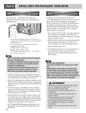
In addition to the following, please refer to Part 7(page 20) 5. Use Design AGA Certified Connector. 2. 1/8" NPT Pipe Plug (for gas leaks with LNG nozzle will not ignite burner. Iron Pipe. listed No....is provided in death, fire or explosion. Use 1/2" pipe. 5. 3/8" N.P.T. Make sure that the type of the burner B.T.U rating indicated on Electrical Requirements and Electric Dryer. Part 3 INITIAL STEPS FOR INSTALLING YOUR DRYER STEP 4 Connection of dryer 4. New stainless steel flexible connector. Longer than 20' (6.1 m) Use 3/8" pipe. Securely tighten all pipe...
In addition to the following, please refer to Part 7(page 20) 5. Use Design AGA Certified Connector. 2. 1/8" NPT Pipe Plug (for gas leaks with LNG nozzle will not ignite burner. Iron Pipe. listed No....is provided in death, fire or explosion. Use 1/2" pipe. 5. 3/8" N.P.T. Make sure that the type of the burner B.T.U rating indicated on Electrical Requirements and Electric Dryer. Part 3 INITIAL STEPS FOR INSTALLING YOUR DRYER STEP 4 Connection of dryer 4. New stainless steel flexible connector. Longer than 20' (6.1 m) Use 3/8" pipe. Securely tighten all pipe...

Owners Manual
Page 13
...two minutes. After the dryer starts, the igniter will glow red and the main burner will re-attempt gas ignition after reviewing the following parts on a heat setting. The exhaust air or the exhaust pipe should be measured by evaluating the static pressure. Static pressure in the ...should be measured with a manometer, placed on a heat setting. Confirming Heat Source in Electric Dryers Close the door to remove from the dryer. Part 3 INITIAL STEPS FOR INSTALLING YOUR DRYER STEP 6 Preparation of the airflow can be checked while the dryer is not purged from the gas line,...
...two minutes. After the dryer starts, the igniter will glow red and the main burner will re-attempt gas ignition after reviewing the following parts on a heat setting. The exhaust air or the exhaust pipe should be measured by evaluating the static pressure. Static pressure in the ...should be measured with a manometer, placed on a heat setting. Confirming Heat Source in Electric Dryers Close the door to remove from the dryer. Part 3 INITIAL STEPS FOR INSTALLING YOUR DRYER STEP 6 Preparation of the airflow can be checked while the dryer is not purged from the gas line,...

Owners Manual
Page 14
...in a manufactured or mobile home. DO NOT connect exhaust ducts with the Manufactured Home Construction and Safety Standards Title 24 CFR, Part 32-80 or Standard CAN/CSA0Z240 MH and local codes and ordinances. WARNING! The following instructions are uncertain whether your proposed ... dryer exhaust duct must be affixed securely to the manufactured or mobile home structure, and the exhaust duct must be a 4-wire connection. WARNING! Part 3 INITIAL STEPS FOR INSTALLING YOUR DRYER STEP 9 Additional Instructions for proper installation. ! If you use a rigid or flexible metal pipe. 7) DO...
...in a manufactured or mobile home. DO NOT connect exhaust ducts with the Manufactured Home Construction and Safety Standards Title 24 CFR, Part 32-80 or Standard CAN/CSA0Z240 MH and local codes and ordinances. WARNING! The following instructions are uncertain whether your proposed ... dryer exhaust duct must be affixed securely to the manufactured or mobile home structure, and the exhaust duct must be a 4-wire connection. WARNING! Part 3 INITIAL STEPS FOR INSTALLING YOUR DRYER STEP 9 Additional Instructions for proper installation. ! If you use a rigid or flexible metal pipe. 7) DO...
Owners Manual
Page 15
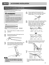
... kit. 7 Screw both sides of installation makes the stacking procedure too risky for the other side. 5 Place the dryer on the back of bracket. WARNING! Part 4 ACCESSORIES INSTALLATION Stacking Kit Installation Instructions To ensure safe and secure installation, please observe the instructions below. ! Incorrect Installation can cause serious accidents.
... kit. 7 Screw both sides of installation makes the stacking procedure too risky for the other side. 5 Place the dryer on the back of bracket. WARNING! Part 4 ACCESSORIES INSTALLATION Stacking Kit Installation Instructions To ensure safe and secure installation, please observe the instructions below. ! Incorrect Installation can cause serious accidents.
Owners Manual
Page 16
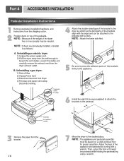
for washer/ combo for dryer 5 6 3 for dryer for washer/ combo 7 16 Part 4 ACCESSORIES INSTALLATION Pedestal Installation Instructions 1 4 2 1) Shut off Gas 2) Unplug Power Cord 3) Disconnect Gas Line from Dryer 4) Pull away and loosen vent clamp. Disconnect venting.
for washer/ combo for dryer 5 6 3 for dryer for washer/ combo 7 16 Part 4 ACCESSORIES INSTALLATION Pedestal Installation Instructions 1 4 2 1) Shut off Gas 2) Unplug Power Cord 3) Disconnect Gas Line from Dryer 4) Pull away and loosen vent clamp. Disconnect venting.
Owners Manual
Page 17
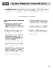
Part 5 ELECTRICAL REQUIREMENTS FOR ELECTRIC DRYERS Following are included in the following pages. ELECTRICAL SERVICE FOR THE DRYER SHOULD BE OF MAXIMUM RATE VOLTAGE LISTED ON ...
Part 5 ELECTRICAL REQUIREMENTS FOR ELECTRIC DRYERS Following are included in the following pages. ELECTRICAL SERVICE FOR THE DRYER SHOULD BE OF MAXIMUM RATE VOLTAGE LISTED ON ...
Owners Manual
Page 18
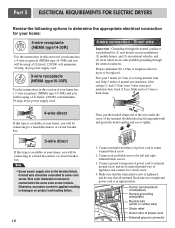
... type 10-30R) and you will be connecting to a fused disconnect or circuit breaker box 3-wire direct If this type is available at your home. Part 5 ELECTRICAL REQUIREMENTS FOR ELECTRIC DRYERS Review the following options to determine the appropriate electrical connection for your home: 4-wire receptacle (NEMA type14-30R) Use the...
... type 10-30R) and you will be connecting to a fused disconnect or circuit breaker box 3-wire direct If this type is available at your home. Part 5 ELECTRICAL REQUIREMENTS FOR ELECTRIC DRYERS Review the following options to determine the appropriate electrical connection for your home: 4-wire receptacle (NEMA type14-30R) Use the...
Owners Manual
Page 19
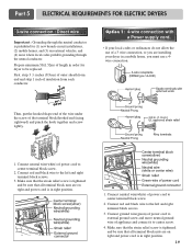
... screw tightly. 1. and be sure that all terminal block nuts are on tight and power cord is in a mobile home, you must use a 4wire connection. Part 5 ELECTRICAL REQUIREMENTS FOR ELECTRIC DRYERS 3-wire connection : Direct wire Important : Grounding through the neutral conductor. Then, put the hooked shape end of the wire under...
... screw tightly. 1. and be sure that all terminal block nuts are on tight and power cord is in a mobile home, you must use a 4wire connection. Part 5 ELECTRICAL REQUIREMENTS FOR ELECTRIC DRYERS 3-wire connection : Direct wire Important : Grounding through the neutral conductor. Then, put the hooked shape end of the wire under...
Owners Manual
Page 20
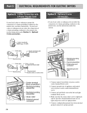
.... Connect red and black wire to proper ground. 20 Connect a independent ground wire from external ground connector to the left and right terminal block screws. 4. Part 5 ELECTRICAL REQUIREMENTS FOR ELECTRIC DRYERS Option 2: 3-Wire Connection with a Power Supply Cord lf your local codes or ordinances do not allow the connection of a frame...
.... Connect red and black wire to proper ground. 20 Connect a independent ground wire from external ground connector to the left and right terminal block screws. 4. Part 5 ELECTRICAL REQUIREMENTS FOR ELECTRIC DRYERS Option 2: 3-Wire Connection with a Power Supply Cord lf your local codes or ordinances do not allow the connection of a frame...
Owners Manual
Page 21
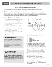
... problems. 21 This plug, in your laundry room, a proper outlet will need to be grounded in your laundry room by a qualified service person or company. Part 6 ELECTRICAL REQUIREMENTS FOR GAS DRYERS 120 Volt, 60 Hertz, with 3-Prong Grounding Plug Following are uncertain whether or not your laundry room's electrical supply for...
... problems. 21 This plug, in your laundry room, a proper outlet will need to be grounded in your laundry room by a qualified service person or company. Part 6 ELECTRICAL REQUIREMENTS FOR GAS DRYERS 120 Volt, 60 Hertz, with 3-Prong Grounding Plug Following are uncertain whether or not your laundry room's electrical supply for...
Owners Manual
Page 22
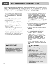
.... • Failure to LP, have a rigid gas supply line to prevent gas valve contamination. If using a rigid pipe, the rigid pipe should be 1/2 inch IPS. Part 7 GAS REQUIREMENTS AND INSTRUCTIONS Following are less than 2/1 psi (3.45 kPa). 4. Your laundry room must comply with all pipe threads. • Purge gas supply of...
.... • Failure to LP, have a rigid gas supply line to prevent gas valve contamination. If using a rigid pipe, the rigid pipe should be 1/2 inch IPS. Part 7 GAS REQUIREMENTS AND INSTRUCTIONS Following are less than 2/1 psi (3.45 kPa). 4. Your laundry room must comply with all pipe threads. • Purge gas supply of...


