Specification
Page 1
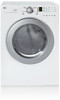
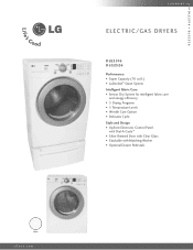
D L E 2 516 D L G 2 5 2 6 L A U N D RY ELECTRIC/GAS DRYERS D L E 2516 DLG2526 Performance • Super Capacity (7.0 cu.ft.) • LoDecibel™ Quiet System Intelligent Fabric Care • Sensor Dry System for intelligent fabric care and energy efficiency • 5 Drying Programs • 5 Temperature Levels • Wrinkle Care Option • Delicates Cycle Style and Design • Upfront Electronic Control Panel with Dial-A-Cycle™ • Silver Rimmed Door with Clear Glass • Stackable with Matching Washer • Optional Drawer Pedestals White LGusa.com
D L E 2 516 D L G 2 5 2 6 L A U N D RY ELECTRIC/GAS DRYERS D L E 2516 DLG2526 Performance • Super Capacity (7.0 cu.ft.) • LoDecibel™ Quiet System Intelligent Fabric Care • Sensor Dry System for intelligent fabric care and energy efficiency • 5 Drying Programs • 5 Temperature Levels • Wrinkle Care Option • Delicates Cycle Style and Design • Upfront Electronic Control Panel with Dial-A-Cycle™ • Silver Rimmed Door with Clear Glass • Stackable with Matching Washer • Optional Drawer Pedestals White LGusa.com
Specification
Page 2
...126 / 144 WA R R A N T Y 1 Year Labor and Parts UPC CODE DLE2516W 048231 009096 DLG2526W 048231 009102 WDP3W 048231 008556 WSTK1 048231 008327 Design and specifications are trademarks of their respective owners. LG Design and Life's Good are subject to change without heat to "set it and go... Dry CONVENIENCE FEATURES End of Cycle Beeper Child Lock Venting Option 4-way Venting Option (electric) 3-way Venting Option (gas) Drum Light Heater Multi-Level Control Reversible Door Remaining Time Display/Status Indicator Leveling Legs 4 Adjustable Legs LoDecibel™...
...126 / 144 WA R R A N T Y 1 Year Labor and Parts UPC CODE DLE2516W 048231 009096 DLG2526W 048231 009102 WDP3W 048231 008556 WSTK1 048231 008327 Design and specifications are trademarks of their respective owners. LG Design and Life's Good are subject to change without heat to "set it and go... Dry CONVENIENCE FEATURES End of Cycle Beeper Child Lock Venting Option 4-way Venting Option (electric) 3-way Venting Option (gas) Drum Light Heater Multi-Level Control Reversible Door Remaining Time Display/Status Indicator Leveling Legs 4 Adjustable Legs LoDecibel™...
Service Manual
Page 1
U.S.A. MODEL : DLE2516W/DLG2526W/DLE3733 Website: http://us.lgservice.com Canadian Website: http://lg.ca ELECTRIC & GAS DRYER SERVICE MANUAL CAUTION READ THIS MANUAL CAREFULLY IN ORDER TO PROPERLY DIAGNOSE PROBLEMS AND TO SAFELY PROVIDE QUALITY SERVICE ON THESE DRYERS.
U.S.A. MODEL : DLE2516W/DLG2526W/DLE3733 Website: http://us.lgservice.com Canadian Website: http://lg.ca ELECTRIC & GAS DRYER SERVICE MANUAL CAUTION READ THIS MANUAL CAREFULLY IN ORDER TO PROPERLY DIAGNOSE PROBLEMS AND TO SAFELY PROVIDE QUALITY SERVICE ON THESE DRYERS.
Service Manual
Page 3
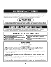
... If electrical power is finished, but failure may damage or weaken the electronic control assembly. If you cannot reach your gas supplier from its package, touch the anti-static bag to ESD stress. IMPORTANT Electrostatic Discharge (ESD) Sensitive Electronics ESD ...part from a neighbor's phone. When repackaging failed electronic control assembly in electrical, electronic, and mechanical appliance repair. Immediately call your gas supplier, call the fire department. The new control assembly may appear to ground are present everywhere. Connect wrist strap to repair ...
... If electrical power is finished, but failure may damage or weaken the electronic control assembly. If you cannot reach your gas supplier from its package, touch the anti-static bag to ESD stress. IMPORTANT Electrostatic Discharge (ESD) Sensitive Electronics ESD ...part from a neighbor's phone. When repackaging failed electronic control assembly in electrical, electronic, and mechanical appliance repair. Immediately call your gas supplier, call the fire department. The new control assembly may appear to ground are present everywhere. Connect wrist strap to repair ...
Service Manual
Page 4
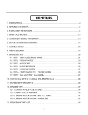
...TEST ...20 9-1. ELECTRIC MODEL 28 9-7. EXPLODED VIEW ...39 12-1. DRUM & MOTOR ASSEMBLY: GAS MODEL 42 13. CONTROL LAYOUT ...18 8. TEST 4 MOISTURE SENSOR 26 9-5. CHANGE GAS SETTING (NATURAL GAS, PROPANE GAS 30 11. CABINET & DOOR ASSEMBLY 40 12-3-1. WIRING DIAGRAM ...19 9. TEST 1 120V... AC ELECTRICAL SUPPLY 21 9-2. TEST 2 THERMISTOR TEST 24 9-3. GAS MODEL 29 10. INSTALLATION INSTRUCTIONS 6 4. CONTROL PANEL ...
...TEST ...20 9-1. ELECTRIC MODEL 28 9-7. EXPLODED VIEW ...39 12-1. DRUM & MOTOR ASSEMBLY: GAS MODEL 42 13. CONTROL LAYOUT ...18 8. TEST 4 MOISTURE SENSOR 26 9-5. CHANGE GAS SETTING (NATURAL GAS, PROPANE GAS 30 11. CABINET & DOOR ASSEMBLY 40 12-3-1. WIRING DIAGRAM ...19 9. TEST 1 120V... AC ELECTRICAL SUPPLY 21 9-2. TEST 2 THERMISTOR TEST 24 9-3. GAS MODEL 29 10. INSTALLATION INSTRUCTIONS 6 4. CONTROL PANEL ...
Service Manual
Page 5
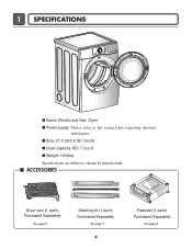
1 SPECIFICATIONS I Name: Electric and Gas Dryer I ACCESSORIES Dryer rack (1 each) Purchased Separately See page 6 Stacking kit (1 each) Purchased Separately See page 7 4 Pedestal (1 each) Purchased Separately See page 8 I Power supply: Please refer to change by manufacturer. I Size: 27 X 29.9 X 38.7 (inch) I Weight: 126(Ibs) Specifications are subject to the rating label regarding detailed information. I Dryer capacity: IEC 7.3 cu.ft.
1 SPECIFICATIONS I Name: Electric and Gas Dryer I ACCESSORIES Dryer rack (1 each) Purchased Separately See page 6 Stacking kit (1 each) Purchased Separately See page 7 4 Pedestal (1 each) Purchased Separately See page 8 I Power supply: Please refer to change by manufacturer. I Size: 27 X 29.9 X 38.7 (inch) I Weight: 126(Ibs) Specifications are subject to the rating label regarding detailed information. I Dryer capacity: IEC 7.3 cu.ft.
Service Manual
Page 6
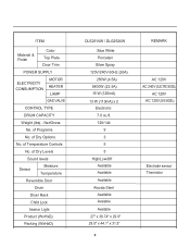
.... of Temperature Controls No. of Dry Levels Sound levels Sensor Moisture Temperature Reversible Door Drum Dryer Rack Child Lock Interior Light Product (WxHxD) Packing (WxHxD) DLE2516W / DLG2526W Blue White Porcelain Silver Spray 120V/240V 60Hz (26A) 250W (4.5A) 5400W (22.5A) 15 W (125mA) 13 W (110mA) x 2 Electronic 7.0 cu.ft. ... 27" x 38.74" x 29.9" 29.5" x 44.1" x 31.3" 5 REMARK AC 120V AC 240V (ELECTRIC MODEL) AC 120V AC 120V (GAS MODEL) Electrode sensor Thermistor ITEM Material & Finish Color Top Plate Door Trim POWER SUPPLY ELECTRICITY CONSUMPTION MOTOR HEATER LAMP...
.... of Temperature Controls No. of Dry Levels Sound levels Sensor Moisture Temperature Reversible Door Drum Dryer Rack Child Lock Interior Light Product (WxHxD) Packing (WxHxD) DLE2516W / DLG2526W Blue White Porcelain Silver Spray 120V/240V 60Hz (26A) 250W (4.5A) 5400W (22.5A) 15 W (125mA) 13 W (110mA) x 2 Electronic 7.0 cu.ft. ... 27" x 38.74" x 29.9" 29.5" x 44.1" x 31.3" 5 REMARK AC 120V AC 240V (ELECTRIC MODEL) AC 120V AC 120V (GAS MODEL) Electrode sensor Thermistor ITEM Material & Finish Color Top Plate Door Trim POWER SUPPLY ELECTRICITY CONSUMPTION MOTOR HEATER LAMP...
Service Manual
Page 8
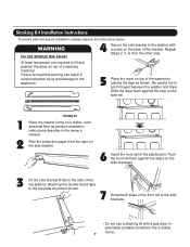
At least two people are required to the washer with a gas dryer in potentially unstable conditions like a mobile home. 7 Failure to heed this alone! 4 Secure the side bracket to lift and position the dryer on the ...
At least two people are required to the washer with a gas dryer in potentially unstable conditions like a mobile home. 7 Failure to heed this alone! 4 Secure the side bracket to lift and position the dryer on the ...
Service Manual
Page 13
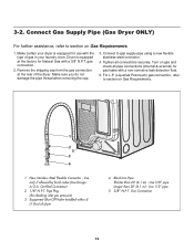
...) for use with a non-corrosive leak detection fluid. 5. Use 3/8" pipe Longer than 20' (6.1 m) - 3-2. For L.P. (Liquefied Petroleum) gas connection, refer to gas supply pipe using a new flexible stainless steel connector. 4. Certified Connector) 2 1/8" N.P.T. Gas Connection 12 Turn on Gas Requirements. 1. Make certain your laundry room. Make sure you do not damage the pipe thread when removing...
...) for use with a non-corrosive leak detection fluid. 5. Use 3/8" pipe Longer than 20' (6.1 m) - 3-2. For L.P. (Liquefied Petroleum) gas connection, refer to gas supply pipe using a new flexible stainless steel connector. 4. Certified Connector) 2 1/8" N.P.T. Gas Connection 12 Turn on Gas Requirements. 1. Make certain your laundry room. Make sure you do not damage the pipe thread when removing...

Service Manual
Page 16
...8226; See Page 13 10. Frame Detect Measure resistance of the following terminal Valve 1 terminal Valve 2 terminal • Gas type Resistance value: > 1.5 kΩ Resistance value: > 1.5~2.5 kΩ 11. Thermistor 9. Gas valve valve 1 Measure resistance of the following terminal Terminal: 1 (COM) - 2 Terminal: 1 (COM) - ...: 20Ω Remark • Electric type Measure resistance of terminal to terminal Resistance value: 100~800Ω • Gas type 12. Component 7. Heater 8. Igniter valve 2 Measure resistance of terminal to terminal Open at 370°F ((Maximum) ...
...8226; See Page 13 10. Frame Detect Measure resistance of the following terminal Valve 1 terminal Valve 2 terminal • Gas type Resistance value: > 1.5 kΩ Resistance value: > 1.5~2.5 kΩ 11. Thermistor 9. Gas valve valve 1 Measure resistance of the following terminal Terminal: 1 (COM) - 2 Terminal: 1 (COM) - ...: 20Ω Remark • Electric type Measure resistance of terminal to terminal Resistance value: 100~800Ω • Gas type 12. Component 7. Heater 8. Igniter valve 2 Measure resistance of terminal to terminal Open at 370°F ((Maximum) ...
Service Manual
Page 17
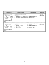
... at 203 ± 7°F (95 ± 5°C) Close at 158 ± 9°F (70 ± 5°C) Check result Resistance value ∞ Continuity < 1Ω Remark • Gas type • Gas funnel Measure resistance of terminal to terminal Open at 212 ± 12°F (100 ± 7°C) Manual reset If thermal fuse is open must...
... at 203 ± 7°F (95 ± 5°C) Close at 158 ± 9°F (70 ± 5°C) Check result Resistance value ∞ Continuity < 1Ω Remark • Gas type • Gas funnel Measure resistance of terminal to terminal Open at 212 ± 12°F (100 ± 7°C) Manual reset If thermal fuse is open must...
Service Manual
Page 20
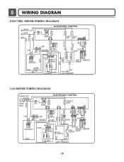
... SWITCH WHITE LAMP YELLOW 1 2 3 BELT SWITCH 1 2 3 7 10 MOTOR OVERLOAD PROTECTOR BLUE HEATER 2 1 2 1 MOISTURE THERMISTOR SENSOR CENTRIFUGAL SWITCH BLOWER WHITE THERMOSTAT RED RED HI - LIMIT THERMOSTAT GAS DRYER WIRING DIAGRAM POWER CORD L1 BLACK N WHITE GN/YL WHITE 1 WH1 TRANS BL2 3 1 ELECTRONIC CONTROL YL2 1 3 TAB RELAY BLACK BL3 123 NA6 6 5 4321 RED...
... SWITCH WHITE LAMP YELLOW 1 2 3 BELT SWITCH 1 2 3 7 10 MOTOR OVERLOAD PROTECTOR BLUE HEATER 2 1 2 1 MOISTURE THERMISTOR SENSOR CENTRIFUGAL SWITCH BLOWER WHITE THERMOSTAT RED RED HI - LIMIT THERMOSTAT GAS DRYER WIRING DIAGRAM POWER CORD L1 BLACK N WHITE GN/YL WHITE 1 WH1 TRANS BL2 3 1 ELECTRONIC CONTROL YL2 1 3 TAB RELAY BLACK BL3 123 NA6 6 5 4321 RED...
Service Manual
Page 21
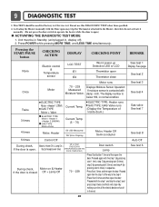
...times and then open Thermistor close See test 1 Display: See page See test 2 Once Motor Motor runs 70 ~ 239 Measured Moisture Value. Gas valve See test 7 See test 8 Auto Off See test 6 20 Do not use this DIAGNOSTIC TEST other than specified. 2. Unit must be... See test 4 Twice 3 times ELECTRIC TYPE Motor + Heater 1 (2700W) GAS TYPE Motor + Valve ELECTRIC TYPE Motor + Heater 1 +Heater 2 (5400W) GAS TYPE Motor+Valve Current Temp. Current Temp. (5 ~ 70) ELECTRIC TYPE: Heater runs GAS TYPE: GAS Valve runs (Display the Temperature of Inside drum.) 4 times Motor, Heater 50...
...times and then open Thermistor close See test 1 Display: See page See test 2 Once Motor Motor runs 70 ~ 239 Measured Moisture Value. Gas valve See test 7 See test 8 Auto Off See test 6 20 Do not use this DIAGNOSTIC TEST other than specified. 2. Unit must be... See test 4 Twice 3 times ELECTRIC TYPE Motor + Heater 1 (2700W) GAS TYPE Motor + Valve ELECTRIC TYPE Motor + Heater 1 +Heater 2 (5400W) GAS TYPE Motor+Valve Current Temp. Current Temp. (5 ~ 70) ELECTRIC TYPE: Heater runs GAS TYPE: GAS Valve runs (Display the Temperature of Inside drum.) 4 times Motor, Heater 50...
Service Manual
Page 23
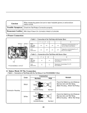
... an electric shock. Caution When measuring power, be sure to wear insulated gloves, to Controller. 1.Power Connection < Table1 > : Connection of the Tab Relay with Burner (Gas) High Mid High Medium Low Extra Low Ta B O O O O R Temperature Control below 70 4°C. Trouble Symptom Check the Tab Relays Connection properly. Black Tab Relay) Tap...
... an electric shock. Caution When measuring power, be sure to wear insulated gloves, to Controller. 1.Power Connection < Table1 > : Connection of the Tab Relay with Burner (Gas) High Mid High Medium Low Extra Low Ta B O O O O R Temperature Control below 70 4°C. Trouble Symptom Check the Tab Relays Connection properly. Black Tab Relay) Tap...
Service Manual
Page 24
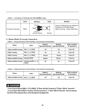
...condition Of operation Power Off Power Off Power On Power On Power Off < Table2 > : Wrong Connection of Tab Relay with PCB ASSEMBLY (Gas) Color Harness PCB Connector Housing Black Blue Wire 1 2 Black Wire Connector Housing Tap relay 1 Remark Check the Matching color Between Harness ...wire and Tab Relay. (Black Housing - < Table 2 > : Connection of the Tab Relay and Connector Housing (Gas) Items Case Heater1 Heater2 Operation(black) operation(White) 1.Black and White Housing Wire , CROSS Off Off PCB condition Of operation Power Off !
...condition Of operation Power Off Power Off Power On Power On Power Off < Table2 > : Wrong Connection of Tab Relay with PCB ASSEMBLY (Gas) Color Harness PCB Connector Housing Black Blue Wire 1 2 Black Wire Connector Housing Tap relay 1 Remark Check the Matching color Between Harness ...wire and Tab Relay. (Black Housing - < Table 2 > : Connection of the Tab Relay and Connector Housing (Gas) Items Case Heater1 Heater2 Operation(black) operation(White) 1.Black and White Housing Wire , CROSS Off Off PCB condition Of operation Power Off !
Service Manual
Page 30
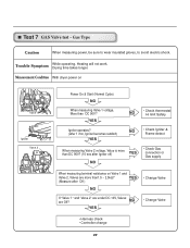
...and Valve 2, Valves are Off? YES NO • Check thermostat Hi limit Safety Igniter operates? (after Igniter off) YES NO • Check Gas connection or Gas supply When measuring terminal resistance on Valve 1 Igniter Valve 2 Power On & Start (Normal Cycle) NO When measuring Valve 1 voltage, More than ...Frame detect When measuring Valve 2 voltage, Value is more than1.5 ~ 2.5kΩ? Trouble Symptom While operating, Heating will not work. Test 7 GAS Valve test - Gas Type Caution When measuring power, be sure to wear insulated gloves, to avoid electric shock.
...and Valve 2, Valves are Off? YES NO • Check thermostat Hi limit Safety Igniter operates? (after Igniter off) YES NO • Check Gas connection or Gas supply When measuring terminal resistance on Valve 1 Igniter Valve 2 Power On & Start (Normal Cycle) NO When measuring Valve 1 voltage, More than ...Frame detect When measuring Valve 2 voltage, Value is more than1.5 ~ 2.5kΩ? Trouble Symptom While operating, Heating will not work. Test 7 GAS Valve test - Gas Type Caution When measuring power, be sure to wear insulated gloves, to avoid electric shock.
Service Manual
Page 31
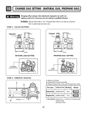
... screw STEP 2 : ORIFICE CHANGE Orifice Close Adjustment screw Remove 2 screws. Initially, Natural Gas mode is on sale as a Service Part to authorized servicers only. Gas type Orifice P/No Marking Shape Natural Gas 4948EL4001B NCU Propane Gas 4948EL4002B PCU Kit contents: Orifice (Dia. = 1.613mm, for Propane Gas) Replace Label Instruction Sheet 30 Warning Changing orifices and...
... screw STEP 2 : ORIFICE CHANGE Orifice Close Adjustment screw Remove 2 screws. Initially, Natural Gas mode is on sale as a Service Part to authorized servicers only. Gas type Orifice P/No Marking Shape Natural Gas 4948EL4001B NCU Propane Gas 4948EL4002B PCU Kit contents: Orifice (Dia. = 1.613mm, for Propane Gas) Replace Label Instruction Sheet 30 Warning Changing orifices and...

Service Manual
Page 32
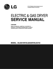
GAS VALVE FLOW START KEY PUSH VALVE 1 ON (VALVE 2 OFF) IGNITER ON IGNITER NO TEMPERATURE ABOUT 370°F YES FLAME DETECT OPEN IGNITER OFF VALVE 2 ON GAS IGNITION YES DRYING NO FLAME DETECT CLOSE VALVE 2 OFF GAS IGNITION START VALVE 1 IGNITER FLAME DETECT VALVE 2 ON ON CLOSE OFF OFF OPEN ON GAS IGNITION GAS VALVE STRUCTURE Adjustment Screw 31
GAS VALVE FLOW START KEY PUSH VALVE 1 ON (VALVE 2 OFF) IGNITER ON IGNITER NO TEMPERATURE ABOUT 370°F YES FLAME DETECT OPEN IGNITER OFF VALVE 2 ON GAS IGNITION YES DRYING NO FLAME DETECT CLOSE VALVE 2 OFF GAS IGNITION START VALVE 1 IGNITER FLAME DETECT VALVE 2 ON ON CLOSE OFF OFF OPEN ON GAS IGNITION GAS VALVE STRUCTURE Adjustment Screw 31
Service Manual
Page 37
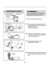
... duct. 36 DUCT TAPE 2-2. DUCT TAPE 3-2. Detach and remove a knockout at the botton, left or right side as desired. (Right Side Vent not available on Gas dryer the order of work. Wrap duct tape around joint. Insert the elbow duct assembly through the side opening and connect the elbow to take...
... duct. 36 DUCT TAPE 2-2. DUCT TAPE 3-2. Detach and remove a knockout at the botton, left or right side as desired. (Right Side Vent not available on Gas dryer the order of work. Wrap duct tape around joint. Insert the elbow duct assembly through the side opening and connect the elbow to take...
Owners Manual
Page 1
P/No.: 3828EL3004F P/No.: 3828EL3003B Electric and Gas Dryer DLE2516W / DLG2526W Thank you for future reference. Record the Model and Serial Numbers, and retain the manual for buying a LG Dryer. Please read your manual carefully, as it provides instructions on safe Installation, Use and Maintenance.
P/No.: 3828EL3004F P/No.: 3828EL3003B Electric and Gas Dryer DLE2516W / DLG2526W Thank you for future reference. Record the Model and Serial Numbers, and retain the manual for buying a LG Dryer. Please read your manual carefully, as it provides instructions on safe Installation, Use and Maintenance.


