
Owner's Manual
Page 1
OWNER'S MANUAL PLASMA TV Please read this manual carefully before operating your set and retain it for future reference. 42PT200 50PT200 42PT350 50PT350 60PV250 50PV400 60PV400 50PV450 60PV450 42PT250U 50PT250U 50PV550U 60PV550U 42PT350C 50PT350C 50PV450C 60PV450C P/NO : SAC34173308 (1109-REV04) www.lg.com
OWNER'S MANUAL PLASMA TV Please read this manual carefully before operating your set and retain it for future reference. 42PT200 50PT200 42PT350 50PT350 60PV250 50PV400 60PV400 50PV450 60PV450 42PT250U 50PT250U 50PV550U 60PV550U 42PT350C 50PT350C 50PV450C 60PV450C P/NO : SAC34173308 (1109-REV04) www.lg.com

Owner's Manual
Page 2
NOTE TO CABLE/TV INSTALLER This reminder is connected. - The code provides guidelines for compliance could void the user's authority to correct the interference by turning the equipment off and on a circuit different from LG Electronics. To prevent fire or shock hazards, do not ...separation between the equipment and receiver. - Operation is intended to alert the user to persons. Consult the dealer or an experienced radio/TV technician for a Class B digital device, pursuant to the following measures: - Any changes or modifications not expressly approved by the party ...
NOTE TO CABLE/TV INSTALLER This reminder is connected. - The code provides guidelines for compliance could void the user's authority to correct the interference by turning the equipment off and on a circuit different from LG Electronics. To prevent fire or shock hazards, do not ...separation between the equipment and receiver. - Operation is intended to alert the user to persons. Consult the dealer or an experienced radio/TV technician for a Class B digital device, pursuant to the following measures: - Any changes or modifications not expressly approved by the party ...

Owner's Manual
Page 4
...electric shock (i.e. The plug must be certain. Pay particular attention to the same AC power outlet as gasoline or candles or expose the TV to direct air conditioning. 16 Do not expose to a three-prong grounded AC outlet). Do not use of this apparatus or antenna during... the power cord. Check the specification page of the appliance, and have a qualified electrician install a separate circuit breaker. Do not touch the TV with an exact replacement part by connecting it , discontinue use a damaged or loose power cord. on the power cord to telephone wires, lightening...
...electric shock (i.e. The plug must be certain. Pay particular attention to the same AC power outlet as gasoline or candles or expose the TV to direct air conditioning. 16 Do not expose to a three-prong grounded AC outlet). Do not use of this apparatus or antenna during... the power cord. Check the specification page of the appliance, and have a qualified electrician install a separate circuit breaker. Do not touch the TV with an exact replacement part by connecting it , discontinue use a damaged or loose power cord. on the power cord to telephone wires, lightening...
Owner's Manual
Page 5
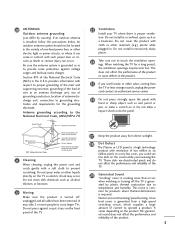
...press against voltage surges and built-up static charges. mon for the grounding electrode. It varies depending on the screen while you'reviewing the TV. An outdoor antenna system should not be located in contact with cloth or other odors coming from a high-speed switching circuit, which ... reliability of two million to six million pixels. Antenna grounding according to the National Electrical Code, ANSI/NFPA 70 23 Ventilation Install your TV where there is com- NEC: National Electrical Code 21 Cleaning When cleaning, unplug the power cord and scrub gently with chemicals such as...
...press against voltage surges and built-up static charges. mon for the grounding electrode. It varies depending on the screen while you'reviewing the TV. An outdoor antenna system should not be located in contact with cloth or other odors coming from a high-speed switching circuit, which ... reliability of two million to six million pixels. Antenna grounding according to the National Electrical Code, ANSI/NFPA 70 23 Ventilation Install your TV where there is com- NEC: National Electrical Code 21 Cleaning When cleaning, unplug the power cord and scrub gently with chemicals such as...
Owner's Manual
Page 6
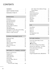
...72 Energy Saving 74 Preset Picture Settings (Picture Mode 75 Manual Picture Adjustment - CONTENTS WARNING 2 SAFETY INSTRUCTIONS 3 FEATURE OF THIS TV 8 PREPARATION Accessories 9 Front Panel Information 10 Back Panel Information 11 Stand Instruction 13 Cable Management 15 Desktop Pedestal Installation 16 Swivel ... 25 Other A/V Source Setup 26 USB Connection 26 Audio Out Connection 27 PC Setup 28 WATCHING TV / CHANNEL CONTROL Remote Control Functions 34 Turning On TV 36 Channel Selection 36 Volume Adjustment 36 Initial Setting 37 On-Screen Menus Selection 38 Quick Menu ...
...72 Energy Saving 74 Preset Picture Settings (Picture Mode 75 Manual Picture Adjustment - CONTENTS WARNING 2 SAFETY INSTRUCTIONS 3 FEATURE OF THIS TV 8 PREPARATION Accessories 9 Front Panel Information 10 Back Panel Information 11 Stand Instruction 13 Cable Management 15 Desktop Pedestal Installation 16 Swivel ... 25 Other A/V Source Setup 26 USB Connection 26 Audio Out Connection 27 PC Setup 28 WATCHING TV / CHANNEL CONTROL Remote Control Functions 34 Turning On TV 36 Channel Selection 36 Volume Adjustment 36 Initial Setting 37 On-Screen Menus Selection 38 Quick Menu ...

Owner's Manual
Page 7
Caption Option 95 TIME SETTING Clock Setting - User Mode 85 Infinite Surround 86 Balance 87 TV Speakers On/Off Setup 88 Audio Reset 89 Stereo/SAP Broadcast Setup 90 Audio Language 91 On-Screen Menus Language Selection 92 Caption Mode - ... Setting 98 Sleep Timer Setting 99 Auto Shut-Off Setting 99 PARENTAL CONTROL / RATINGS Set Password & Lock System 100 Channel Blocking 103 Movie & TV Rating 104 Downloadable Rating 109 External Input Blocking 110 Key lock 111 APPENDIX Troubleshooting 112 Maintenance 114 Product Specifications 114 IR Codes 116 External Control...
Caption Option 95 TIME SETTING Clock Setting - User Mode 85 Infinite Surround 86 Balance 87 TV Speakers On/Off Setup 88 Audio Reset 89 Stereo/SAP Broadcast Setup 90 Audio Language 91 On-Screen Menus Language Selection 92 Caption Mode - ... Setting 98 Sleep Timer Setting 99 Auto Shut-Off Setting 99 PARENTAL CONTROL / RATINGS Set Password & Lock System 100 Channel Blocking 103 Movie & TV Rating 104 Downloadable Rating 109 External Input Blocking 110 Key lock 111 APPENDIX Troubleshooting 112 Maintenance 114 Product Specifications 114 IR Codes 116 External Control...
Owner's Manual
Page 8
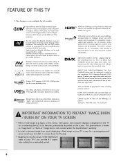
... on how to watch and which can be made through USB 2.0 ('videos' dependent on model). A subset of your registration. This TV contains the detailed calibrations necessary for more information on the screen. Detailed calibration requires a licensed technician. "Dolby "and the double-D symbol... are trademarks of ambient light, LG's "Intelligent Sensor" uses 4,096 sensing steps to convert your TV through the ISFccc mode. Go to vod.divx.com for an extended period, it 's surroundings, more pleasing...
... on how to watch and which can be made through USB 2.0 ('videos' dependent on model). A subset of your registration. This TV contains the detailed calibrations necessary for more information on the screen. Detailed calibration requires a licensed technician. "Dolby "and the double-D symbol... are trademarks of ambient light, LG's "Intelligent Sensor" uses 4,096 sensing steps to convert your TV through the ISFccc mode. Go to vod.divx.com for an extended period, it 's surroundings, more pleasing...

Owner's Manual
Page 9
...ferrite core to reduce the electromagnetic interference in the power cable. If there is missing, please contact the dealer where you purchased the TV. Excessive pressure may differ from the images below. Place the ferrite core close to a wall plug. [to a wall plug] [...the TV and a wall plug. [to a wall plug] [to reduce the electromagnetic interference in the power cable. PREPARATION Owner's Manual CD Manual (For 42/50PT200, 42/50PT350, 42/50PT350C, 42/50PT250U, 50PV400, 50PV450, 50PV450C, 50PV550U) Protection Cover and Tape (Refer to P.14) (For 60PV250, 60PV400, 60PV450...
...ferrite core to reduce the electromagnetic interference in the power cable. If there is missing, please contact the dealer where you purchased the TV. Excessive pressure may differ from the images below. Place the ferrite core close to a wall plug. [to a wall plug] [...the TV and a wall plug. [to a wall plug] [to reduce the electromagnetic interference in the power cable. PREPARATION Owner's Manual CD Manual (For 42/50PT200, 42/50PT350, 42/50PT350C, 42/50PT250U, 50PV400, 50PV450, 50PV450C, 50PV550U) Protection Cover and Tape (Refer to P.14) (For 60PV250, 60PV400, 60PV450...
Owner's Manual
Page 10
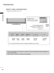
...POWER INPUT Button Button HOME Button ENTER Button VOLUME Buttons You can operate the buttons just by touching them lightly with your TV. The LED is off while the TV remains on the glass stand or subject it to the surrounding conditions. CHANNEL ENTER Buttons G Do not step on . ...G Do not drag the TV. It may break, causing possible injury from your finger. PREPARATION PREPARATION FRONT PANEL INFORMATION I Image shown may differ from fragments of glass, or the TV may fall. The floor or the product may be damaged. 10
...POWER INPUT Button Button HOME Button ENTER Button VOLUME Buttons You can operate the buttons just by touching them lightly with your TV. The LED is off while the TV remains on the glass stand or subject it to the surrounding conditions. CHANNEL ENTER Buttons G Do not step on . ...G Do not drag the TV. It may break, causing possible injury from your finger. PREPARATION PREPARATION FRONT PANEL INFORMATION I Image shown may differ from fragments of glass, or the TV may fall. The floor or the product may be damaged. 10

Owner's Manual
Page 12
... theater systems. Note: In standby mode, this jack. Supports standard definition video only (480i). 8 ANTENNA/CABLE IN Connect over-the air signals to operate the TV on DC power. 12 Uses a D-sub 15 pin cable (VGA cable). 5 REMOTE CONTROL IN PORT For a wired remote control. 6 COMPONENT IN Analog Connection. Doesn't support...
... theater systems. Note: In standby mode, this jack. Supports standard definition video only (480i). 8 ANTENNA/CABLE IN Connect over-the air signals to operate the TV on DC power. 12 Uses a D-sub 15 pin cable (VGA cable). 5 REMOTE CONTROL IN PORT For a wired remote control. 6 COMPONENT IN Analog Connection. Doesn't support...

Owner's Manual
Page 13
... side down on a cushioned surface to protect the screen from your TV. x 4 M4x28 (For 60PV250, 60PV400, 60PV450, 60PV450C, 60PV550U) x 4 M4x26 (For 42/50PT200, 42/50PT350, 42/50PT350C, 42/50PT250U, 50PV400, 50PV450, 50PV450C, 50PV550U) 13 x 3 M5x14.5 (For 42/50PT200, 42/50PT350, 42/...
... side down on a cushioned surface to protect the screen from your TV. x 4 M4x28 (For 60PV250, 60PV400, 60PV450, 60PV450C, 60PV550U) x 4 M4x26 (For 42/50PT200, 42/50PT350, 42/50PT350C, 42/50PT250U, 50PV400, 50PV450, 50PV450C, 50PV550U) 13 x 3 M5x14.5 (For 42/50PT200, 42/50PT350, 42/...

Owner's Manual
Page 14
x 4 M4x28 (For 60PV250, 60PV400, 60PV450, 60PV450C, 60PV550U) x 4 M4x26 (For 42/50PT200, 42/50PT350, 42/50PT350C, 42/50PT250U, 50PV400, 50PV450, 50PV450C, 50PV550U) 3 Detach the stand from TV. Attach the protection cover tape. PREPARATION PREPARATION Detachment 1 Carefully place the TV screen side down on a cushioned surface ...to the Outsides. PROTECTION COVER Fix a Guide to protect the screen from damage. 2 Loose the screws from TV. 4 After removing the stand, install the included PROTECTION COVER over the hole for the stand. When installing the wall ...
x 4 M4x28 (For 60PV250, 60PV400, 60PV450, 60PV450C, 60PV550U) x 4 M4x26 (For 42/50PT200, 42/50PT350, 42/50PT350C, 42/50PT250U, 50PV400, 50PV450, 50PV450C, 50PV550U) 3 Detach the stand from TV. Attach the protection cover tape. PREPARATION PREPARATION Detachment 1 Carefully place the TV screen side down on a cushioned surface ...to the Outsides. PROTECTION COVER Fix a Guide to protect the screen from damage. 2 Loose the screws from TV. 4 After removing the stand, install the included PROTECTION COVER over the hole for the stand. When installing the wall ...

Owner's Manual
Page 15
It will help prevent the power cable from your TV. 1 Install the power cord holder and power cord. POWER CORD HOLDER CABLE HOLDER CAUTION G Do not move the TV by holding the cable holder and power cord holder, as the cable holders may break, and injuries and damage to the TV may differ from being removed by accident. 2 Gather and bind the cables with the cable holder. PREPARATION CABLE MANAGEMENT I Image shown may occur. 15
It will help prevent the power cable from your TV. 1 Install the power cord holder and power cord. POWER CORD HOLDER CABLE HOLDER CAUTION G Do not move the TV by holding the cable holder and power cord holder, as the cable holders may break, and injuries and damage to the TV may differ from being removed by accident. 2 Gather and bind the cables with the cable holder. PREPARATION CABLE MANAGEMENT I Image shown may occur. 15
Owner's Manual
Page 16
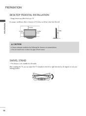
For proper ventilation, allow a clearance of heat source. After installing the TV, you can adjust the TV manually to the left or right direction by following the clearance recommendations. SWIVEL STAND I Image shown may differ from the wall. 4 inches 4 inches 4 inches 4 inches CAUTION G Ensure adequate ventilation by 20 degrees to suit your TV. PREPARATION PREPARATION DESKTOP PEDESTAL INSTALLATION I This feature is not available for all four sides from your viewing position. 16 G Do not mount near or above any type of 4 inches on all models.
For proper ventilation, allow a clearance of heat source. After installing the TV, you can adjust the TV manually to the left or right direction by following the clearance recommendations. SWIVEL STAND I Image shown may differ from the wall. 4 inches 4 inches 4 inches 4 inches CAUTION G Ensure adequate ventilation by 20 degrees to suit your TV. PREPARATION PREPARATION DESKTOP PEDESTAL INSTALLATION I This feature is not available for all four sides from your viewing position. 16 G Do not mount near or above any type of 4 inches on all models.

Owner's Manual
Page 17
... then the standard dimension, as they may fall , leading to the TV. LG recommends that do not comply with the VESA standard screw specifications, the length of accidents. G Standard dimensions for TV damage or personal injury when a non-VESA or non specified wall mount... * 400 M6 4 PSW400BG 50PV450C, 42/50PT250U, 50PV550U 60PV250, 60PV400, 60PV450, 60PV450C, 60PV550U 600 * 400 M8 4 PSW600B, PSW600BG ! G LG is used . We recommend that do not comply with the mount. It may damage the TV or cause the TV to the floor. NOTE G Screw length needed depends on ....
... then the standard dimension, as they may fall , leading to the TV. LG recommends that do not comply with the VESA standard screw specifications, the length of accidents. G Standard dimensions for TV damage or personal injury when a non-VESA or non specified wall mount... * 400 M6 4 PSW400BG 50PV450C, 42/50PT250U, 50PV550U 60PV250, 60PV400, 60PV450, 60PV450C, 60PV550U 600 * 400 M8 4 PSW600B, PSW600BG ! G LG is used . We recommend that do not comply with the mount. It may damage the TV or cause the TV to the floor. NOTE G Screw length needed depends on ....

Owner's Manual
Page 18
...Use a sturdy rope (sold separately) to tie the rope so it cannot fall over (when not using a wall mount). I Insert the eye-bolts (or TV brackets and bolts) to tighten the product to a wall so it becomes horizontal between the wall and the product. ! I Image shown may differ from your... product has the bolts in the eye-bolts position before inserting the eye-bolts, loosen the bolts. * Insert the eye-bolts or TV brackets/bolts and tighten them securely in a forward direction, potentially causing injury or damaging the product. We recommend that the height of the bracket...
...Use a sturdy rope (sold separately) to tie the rope so it cannot fall over (when not using a wall mount). I Insert the eye-bolts (or TV brackets and bolts) to tighten the product to a wall so it becomes horizontal between the wall and the product. ! I Image shown may differ from your... product has the bolts in the eye-bolts position before inserting the eye-bolts, loosen the bolts. * Insert the eye-bolts or TV brackets/bolts and tighten them securely in a forward direction, potentially causing injury or damaging the product. We recommend that the height of the bracket...
Owner's Manual
Page 19
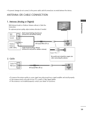
... Multi-family Dwellings/Apartments R Wall (Connect to bRend the copper wire when connecting the antenna. I If the antenna needs to be split for two TV's, install a 2-Way Signal Splitter. PREPARATION () VARIABLE AUDIO OUT R I To improve the picture quality in a poor signal area, please purchase a ...;) ANTENNA /CABLE IN I To prevent damage do not connect to wall jack for assistance. 19 ANTENNA OR CABLE CONNECTION R 1. Cable Cable TV Wall Jack RF Coaxial Wire (75 Ω) Single-family Dwellings /Houses (Connect to the power outlet until all connections are made between the ...
... Multi-family Dwellings/Apartments R Wall (Connect to bRend the copper wire when connecting the antenna. I If the antenna needs to be split for two TV's, install a 2-Way Signal Splitter. PREPARATION () VARIABLE AUDIO OUT R I To improve the picture quality in a poor signal area, please purchase a ...;) ANTENNA /CABLE IN I To prevent damage do not connect to wall jack for assistance. 19 ANTENNA OR CABLE CONNECTION R 1. Cable Cable TV Wall Jack RF Coaxial Wire (75 Ω) Single-family Dwellings /Houses (Connect to the power outlet until all connections are made between the ...
Owner's Manual
Page 20
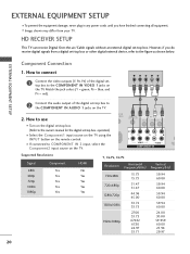
...-top box. (Refer to the owner's manual for the digital set-top box. operation) I Select the Component1 input source on the TV using the INPUT button on the TV. Y PB PR L R 2 Connect the audio output of the digital settop box to the figure as shown below. I Image shown... may differ from a digital set -top box. How to COMPONENT IN 2 input, select the Component2 input source on the TV. I If connected to use I Turn on the TV. 1 2 2. EXTERNAL EQUIPMENT SETUP I To prevent the equipment damage, never plug in any power cords until you do receive digital ...
...-top box. (Refer to the owner's manual for the digital set-top box. operation) I Select the Component1 input source on the TV using the INPUT button on the TV. Y PB PR L R 2 Connect the audio output of the digital settop box to the figure as shown below. I Image shown... may differ from a digital set -top box. How to COMPONENT IN 2 input, select the Component2 input source on the TV. I If connected to use I Turn on the TV. 1 2 2. EXTERNAL EQUIPMENT SETUP I To prevent the equipment damage, never plug in any power cords until you do receive digital ...
Owner's Manual
Page 21
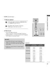
.../DVI IN RS-232C IN (CONTROL & SERVICE) RGB IN(PC) ! In this case use I Select the HDMI1, 2, or 3 input source on the TV using the INPUT button on the TV. 2 No separate audio connection is necessary. HDMI supports both audio and video. 2. HDMI-DTV Resolution Horizontal Frequency(KHz) 720x480p 1280x720p 1920x1080i 1920x1080p...
.../DVI IN RS-232C IN (CONTROL & SERVICE) RGB IN(PC) ! In this case use I Select the HDMI1, 2, or 3 input source on the TV using the INPUT button on the TV. 2 No separate audio connection is necessary. HDMI supports both audio and video. 2. HDMI-DTV Resolution Horizontal Frequency(KHz) 720x480p 1280x720p 1920x1080i 1920x1080p...
Owner's Manual
Page 22
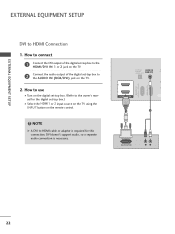
... A DVI to HDMI Connection 1. How to use I Turn on the digital set -top box.) I Select the HDMI1 or 2 input source on the TV using the INPUT button on the TV. 2 Connect the audio output of the digital set-top box to the owner's manual for this connection. DVI doesn't support audio, so... a separate audio connection is required for the digital set -top box. (Refer to the AUDIO IN (RGB/DVI) jack on the TV. 2. OPTICAL AUDIO IN R DIGITAL (RGB/DVI) CO AUDIO OUT RS-232C IN (CONTROL & SERVICE) RGB IN (PC) 2 2 1 1 HDMI/DVI IN 1 2 DVI-DTV OUTPUT R L 22...
... A DVI to HDMI Connection 1. How to use I Turn on the digital set -top box.) I Select the HDMI1 or 2 input source on the TV using the INPUT button on the TV. 2 Connect the audio output of the digital set-top box to the owner's manual for this connection. DVI doesn't support audio, so... a separate audio connection is required for the digital set -top box. (Refer to the AUDIO IN (RGB/DVI) jack on the TV. 2. OPTICAL AUDIO IN R DIGITAL (RGB/DVI) CO AUDIO OUT RS-232C IN (CONTROL & SERVICE) RGB IN (PC) 2 2 1 1 HDMI/DVI IN 1 2 DVI-DTV OUTPUT R L 22...


