
Owners Manual
Page 1
... for future reference. eooa LCD TV I PLASMA TV OWNER'S MANUAL LCD TV MODELS 32LB9D 47LC7DF PLASMA TV MODELS 60PY3D Please read this information to your set. See the [abe[ attached on the back cover and quote this manual carefully before operating your dealer when you require service. Retain [t for energy efficiency...
... for future reference. eooa LCD TV I PLASMA TV OWNER'S MANUAL LCD TV MODELS 32LB9D 47LC7DF PLASMA TV MODELS 60PY3D Please read this information to your set. See the [abe[ attached on the back cover and quote this manual carefully before operating your dealer when you require service. Retain [t for energy efficiency...
Owners Manual
Page 5
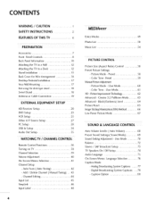
...Modes 49 Photo List 50 Music List 54 PICTURE CONTROL Picture Size (Aspect Ratio) Control .......... 56 Preset Picture Settings - Digital Broadcasting System Captions ...79 - PictureImprovemenTt echnology........... 62 Advanced - Preset 59 ManualPictureAdjustment - Black(Darkness) ...66 Low-Power Picture Mode 67 SOUND & LANGUAGE CONTROL Auto Volume Leveler ( Auto Volume) ......... 68 Preset Sound Settings( Sound Mode) ........ 69 Sound Setting Adjustment - Cinema 3:2 Pulldown Mode ...... 63 Advanced - Auto Scan ( Auto Tuning 42 - Color Tone - ...
...Modes 49 Photo List 50 Music List 54 PICTURE CONTROL Picture Size (Aspect Ratio) Control .......... 56 Preset Picture Settings - Digital Broadcasting System Captions ...79 - PictureImprovemenTt echnology........... 62 Advanced - Preset 59 ManualPictureAdjustment - Black(Darkness) ...66 Low-Power Picture Mode 67 SOUND & LANGUAGE CONTROL Auto Volume Leveler ( Auto Volume) ......... 68 Preset Sound Settings( Sound Mode) ........ 69 Sound Setting Adjustment - Cinema 3:2 Pulldown Mode ...... 63 Advanced - Auto Scan ( Auto Tuning 42 - Color Tone - ...

Owners Manual
Page 6
Auto Clock Setup 81 - Manual Clock Setup 82 Auto On/OffTime Setting 83 Sleep Time Setting 84 Auto Shut-off Setting 85 Z_ ¸ _ 7 =7_Z _ 7_ =_ PARENTAL CONTROL/RATINGS _ _ Set Password & Lock System 86 Channel Blocking 88 Movie & TV Rating 89 External Input Blocking 92 Key Lock 92 APPEND IX Troubleshooting 93 Maintenance 95 Product Specifications 96 Programming the Remote Control .......... 97 IR Codes 101 External Control through RS-232C ......... 103 5 TIME SETTING Clock Setting -
Auto Clock Setup 81 - Manual Clock Setup 82 Auto On/OffTime Setting 83 Sleep Time Setting 84 Auto Shut-off Setting 85 Z_ ¸ _ 7 =7_Z _ 7_ =_ PARENTAL CONTROL/RATINGS _ _ Set Password & Lock System 86 Channel Blocking 88 Movie & TV Rating 89 External Input Blocking 92 Key Lock 92 APPEND IX Troubleshooting 93 Maintenance 95 Product Specifications 96 Programming the Remote Control .......... 97 IR Codes 101 External Control through RS-232C ......... 103 5 TIME SETTING Clock Setting -

Owners Manual
Page 9
m 60PY3D z Remote Control Sensor Program Display Touch Pad Power Standby Indicator • illuminates red in standby mode. • illuminates green when the set is switched on. POWER Button ENTER Button VOLUME MENU Button (@,_) Buttons CHANNEL (T,A) Buttons 8 Then wipe the stand with polishing cloth. FRONT PANELCONTROLS _ Here shown may be somewhat different from your TV. _ If your TV stand has a protection film, remove it attached to the stand.
m 60PY3D z Remote Control Sensor Program Display Touch Pad Power Standby Indicator • illuminates red in standby mode. • illuminates green when the set is switched on. POWER Button ENTER Button VOLUME MENU Button (@,_) Buttons CHANNEL (T,A) Buttons 8 Then wipe the stand with polishing cloth. FRONT PANELCONTROLS _ Here shown may be somewhat different from your TV. _ If your TV stand has a protection film, remove it attached to the stand.

Owners Manual
Page 10
Remote Control Sensor Power/Standby Indicator • illuminates red in standby mode. • illuminates green when the set is switched on . 32LB9D (V,A) Buttons VOLUME (_,_) Buttons Button Button Intelligent Eye Adjusts picture according to the surrounding conditions.... Remote Control Sensor Button Button Power/Standby Indicator • illuminates red in standby mode. • illuminates green when the set is switched on . 9 47LC7DF _D r_ _D (V,A) Buttons VOLUME z (_II,I_) Buttons ENTER Button Button INPUT Button POWER Button Intelligent ...
Remote Control Sensor Power/Standby Indicator • illuminates red in standby mode. • illuminates green when the set is switched on . 32LB9D (V,A) Buttons VOLUME (_,_) Buttons Button Button Intelligent Eye Adjusts picture according to the surrounding conditions.... Remote Control Sensor Button Button Power/Standby Indicator • illuminates red in standby mode. • illuminates green when the set is switched on . 9 47LC7DF _D r_ _D (V,A) Buttons VOLUME z (_II,I_) Buttons ENTER Button Button INPUT Button POWER Button Intelligent ...

Owners Manual
Page 13
... attached to a wall so it cannot be pulled in a forward direction, potentially causing injury or damaging the product. _D Caution: Please make sure that you set up the TV close to the floor/wall per installation instructions.Tipping,shaking, or rocking the machine may be pulled in a forward/backward potentially causing...
... attached to a wall so it cannot be pulled in a forward direction, potentially causing injury or damaging the product. _D Caution: Please make sure that you set up the TV close to the floor/wall per installation instructions.Tipping,shaking, or rocking the machine may be pulled in a forward/backward potentially causing...

Owners Manual
Page 19
... be level with TV. ADDITIONAL COVER SWIVEL STAND (o.ly60PY3D model) After installing the TV, you must close (to the right) the shaft bolt to set manually to the left ) the shaft bolt on the middle of stand's back. z BOLT RUBBER To prevent the foreign materials from entering the desk... stand fixture protection cover(additional cover) by 20 degrees to suit your viewing position. @ Before adjusting the angle, you can adjust the the TV set the hole. 18 NOT USING THE DESK-TYPESTAND(o.'y60PY3D model) _ It is applied to when installing only the 60PY3D model as shown at the figure...
... be level with TV. ADDITIONAL COVER SWIVEL STAND (o.ly60PY3D model) After installing the TV, you must close (to the right) the shaft bolt to set manually to the left ) the shaft bolt on the middle of stand's back. z BOLT RUBBER To prevent the foreign materials from entering the desk... stand fixture protection cover(additional cover) by 20 degrees to suit your viewing position. @ Before adjusting the angle, you can adjust the the TV set the hole. 18 NOT USING THE DESK-TYPESTAND(o.'y60PY3D model) _ It is applied to when installing only the 60PY3D model as shown at the figure...

Owners Manual
Page 21
... box to the figure as This TV supports HDCP (High bandwidth Digital Contents Protection protocol for the digital set . 2. How to use _ Turn on the digital set-top box. (Refer to COMPONENT NENT 2 input source, IN 2 input, select COMPO- However, if you box or other digital ... 1. EXTERNAL EQUIPMENT SETUP HD RECEIVERSETUP This TV can receive Digital Over the-air/Cable do receive digital signals from a digital set-top shown below, signals without an external digital set . Yes No Yes Yes Yes Yes Yes Yes Yes Yes 2O How to connect c O onnect the video outputs (Y, ...
... box to the figure as This TV supports HDCP (High bandwidth Digital Contents Protection protocol for the digital set . 2. How to use _ Turn on the digital set-top box. (Refer to COMPONENT NENT 2 input source, IN 2 input, select COMPO- However, if you box or other digital ... 1. EXTERNAL EQUIPMENT SETUP HD RECEIVERSETUP This TV can receive Digital Over the-air/Cable do receive digital signals from a digital set-top shown below, signals without an external digital set . Yes No Yes Yes Yes Yes Yes Yes Yes Yes 2O How to connect c O onnect the video outputs (Y, ...

Owners Manual
Page 22
... connecting D-sub 15pin cable 1. Now to connect O onnect the RGB output of the set-top box to the -4 AUDIO (RGB/DV[) jack on the set. Z 2. Now to connect O 2 oonrne3ct jatchke odn@thtae[ sseet.t-top box to set . _ Se[ect RGB-PC input source with using the INPUT button on the remote... does not support Auto HDML you need to HDMI/DV[ IN1, O No separated audio connection is necessary, 2. Now to the RGB (PC) jack on the set -top box.) Se[ect HDMI1, HDMI2 or HDMI3 input source with using the INPUT button on the remote control Z -4 -4 c When connecting HDMI cable 1....
... connecting D-sub 15pin cable 1. Now to connect O onnect the RGB output of the set-top box to the -4 AUDIO (RGB/DV[) jack on the set. Z 2. Now to connect O 2 oonrne3ct jatchke odn@thtae[ sseet.t-top box to set . _ Se[ect RGB-PC input source with using the INPUT button on the remote... does not support Auto HDML you need to HDMI/DV[ IN1, O No separated audio connection is necessary, 2. Now to the RGB (PC) jack on the set -top box.) Se[ect HDMI1, HDMI2 or HDMI3 input source with using the INPUT button on the remote control Z -4 -4 c When connecting HDMI cable 1....

Owners Manual
Page 23
How to connect O Connect the DVI output of the digital set-top box to the HDMI/DV[ IN1,2 or 3 lack on the remote controk O Connect the audio output of the digital set-top box to the AUDJO(RGB/DV[) ]ack on the set. 2. How to use Turn on the digital set-top box. (Refer to DVI cable x _3 z r== _D c Z =d m c i 1..i.i.i.:..i.i::1) ........ _ :ifiiii:iil) ii 1. EX""'FERNAELQUIIII!>MENS""E'FTUP When connecting HDMI to the owner's manuaU for the digital set-top box.) Sdect HDMI1, HDMI2 or HDMI3 input source with using the INPUT button on the set.
How to connect O Connect the DVI output of the digital set-top box to the HDMI/DV[ IN1,2 or 3 lack on the remote controk O Connect the audio output of the digital set-top box to the AUDJO(RGB/DV[) ]ack on the set. 2. How to use Turn on the digital set-top box. (Refer to DVI cable x _3 z r== _D c Z =d m c i 1..i.i.i.:..i.i::1) ........ _ :ifiiii:iil) ii 1. EX""'FERNAELQUIIII!>MENS""E'FTUP When connecting HDMI to the owner's manuaU for the digital set-top box.) Sdect HDMI1, HDMI2 or HDMI3 input source with using the INPUT button on the set.

Owners Manual
Page 24
... to connect -4 z O onnect the video outputs (Y, PB, PR) of the DVD to the COMPONENT [N VIDEO1 iacks on the set, _D c Match the iack colors (Y = green, PB = blue, and PR = red), Z -4 O Connect the audio outputs of the DVD to the component input ports as shown ...
... to connect -4 z O onnect the video outputs (Y, PB, PR) of the DVD to the COMPONENT [N VIDEO1 iacks on the set, _D c Match the iack colors (Y = green, PB = blue, and PR = red), Z -4 O Connect the audio outputs of the DVD to the component input ports as shown ...

Owners Manual
Page 25
... is necessary, 2. D_ z 2. m c _ Refer to the DVD player's manual for operating instructions, If the DVD does not support Auto HDM[, you need to set . O Connect the audio outputs of the DVD to the S-VIDEO input on the DVD player, insert a DVD. _sSelect AVl input source with an S-Video cable... 1. Flow to connect O onnect the HDM[ output of the DVD to the HDMJ/DV[ IN1,2 or 5 jack on the set . How to connect O onnect the S-VIDEO output of - EXTERNAL EQUIPMENT SETUP When connecting with using the INPUT button on the remote control Refer to the...
... is necessary, 2. D_ z 2. m c _ Refer to the DVD player's manual for operating instructions, If the DVD does not support Auto HDM[, you need to set . O Connect the audio outputs of the DVD to the S-VIDEO input on the DVD player, insert a DVD. _sSelect AVl input source with an S-Video cable... 1. Flow to connect O onnect the HDM[ output of the DVD to the HDMJ/DV[ IN1,2 or 5 jack on the set . How to connect O onnect the S-VIDEO output of - EXTERNAL EQUIPMENT SETUP When connecting with using the INPUT button on the remote control Refer to the...

Owners Manual
Page 26
... channel number. Now to connect O onnect the RF antenna out socket of the VCR, 2. Insert a video tape into the VCR and press PLAY on the set, Connect the antenna cable to the RF antenna in the Option menu to avoid having a fixed image remain on the screen. How to use...
... channel number. Now to connect O onnect the RF antenna out socket of the VCR, 2. Insert a video tape into the VCR and press PLAY on the set, Connect the antenna cable to the RF antenna in the Option menu to avoid having a fixed image remain on the screen. How to use...

Owners Manual
Page 27
... to use z m Insert a video tape into the VCR and press PLAY on the VCR. (Refer to the AUDIO Mput iacks on the set When connecting with using the INPUT button on rT1 the remote control. z -4 m [t: connected to normal composffe (RCA cable) input. connect the audio came from the ... a RCA cable 1. How to AV IN 2, select AV2 input source. 26 CAUTION and S:Video at €he same time: Connect the audio outputs of the set . Match the lack colors(Video = yellow, Audio Left = whffe,and Audio Right = red) x -4 2.
... to use z m Insert a video tape into the VCR and press PLAY on the VCR. (Refer to the AUDIO Mput iacks on the set When connecting with using the INPUT button on rT1 the remote control. z -4 m [t: connected to normal composffe (RCA cable) input. connect the audio came from the ... a RCA cable 1. How to AV IN 2, select AV2 input source. 26 CAUTION and S:Video at €he same time: Connect the audio outputs of the set . Match the lack colors(Video = yellow, Audio Left = whffe,and Audio Right = red) x -4 2.

Owners Manual
Page 28
Match the iack colors. (Video = yellow, Audio Left = whffe, and Audio Right = red) 2. Now to use Select AV2 input source wffh using the INPUT button on the remote control If connected to connect O Connect the AUD[O/V[DEOiacks between TV and external equipment. OTHER A/V SOURCE SETUP 60PY3D, 47LC7DF =,i' s.vD_o 32LB9D m Video Game Set 1. Now to AV IN 1 input, select AVl input source. Operate the corresponding external equ[pmenL x -..4 Z c Z -..4 --4 c Video Game Set 27
Match the iack colors. (Video = yellow, Audio Left = whffe, and Audio Right = red) 2. Now to use Select AV2 input source wffh using the INPUT button on the remote control If connected to connect O Connect the AUD[O/V[DEOiacks between TV and external equipment. OTHER A/V SOURCE SETUP 60PY3D, 47LC7DF =,i' s.vD_o 32LB9D m Video Game Set 1. Now to AV IN 1 input, select AVl input source. Operate the corresponding external equ[pmenL x -..4 Z c Z -..4 --4 c Video Game Set 27

Owners Manual
Page 29
... or consult the manufacturer of the PC to the RGB V (PC) iack on the set, Z -4 O Connect the PC audio output to use Turn on the set . How to the AUDIO (RGB/DV[) lack on the PC and the set , m -4 C 2. D1 x When connecting D-sub 15 pin cable -4 rT1 z 1. Select RGB-PC input source with... EX""'FERNAELQUIIII!>MENS""E'FTUP PC SETUP This TV provides PJug and Hay capability, meaning that the PC adjusts automatkaJJy to connect >. How to the TV's settings.
... or consult the manufacturer of the PC to the RGB V (PC) iack on the set, Z -4 O Connect the PC audio output to use Turn on the set . How to the AUDIO (RGB/DV[) lack on the PC and the set , m -4 C 2. D1 x When connecting D-sub 15 pin cable -4 rT1 z 1. Select RGB-PC input source with... EX""'FERNAELQUIIII!>MENS""E'FTUP PC SETUP This TV provides PJug and Hay capability, meaning that the PC adjusts automatkaJJy to connect >. How to the TV's settings.

Owners Manual
Page 30
ffthe PC does not support Auto DV )ou need to set . 2. How to use _ Turn on the PC and the set _ Select HDMI1, HDMI2 or HDMI3 input source with using the INPUT button on the set. (Use the HDM[ to DV[ cable) O Connect the PC audio output to the HDMI/DV[ IN] 2 ou 3 iack... resolution to DVI cable x -4 z XD c Z -4 -4 c 1. To get the bes_ picture quality, adiust the output resolution of the PC to the AUD[O(RGB/DV D jackon the set the output resolution appropriately.
ffthe PC does not support Auto DV )ou need to set . 2. How to use _ Turn on the PC and the set _ Select HDMI1, HDMI2 or HDMI3 input source with using the INPUT button on the set. (Use the HDM[ to DV[ cable) O Connect the PC audio output to the HDMI/DV[ IN] 2 ou 3 iack... resolution to DVI cable x -4 z XD c Z -4 -4 c 1. To get the bes_ picture quality, adiust the output resolution of the PC to the AUD[O(RGB/DV D jackon the set the output resolution appropriately.

Owners Manual
Page 33
z m c tPoressdsetchte thMeENPUICTbUutRtoEn maenndu,then use • or • button Pserelescst thSecreI_en.button and then use • or • button to Pmreensus, the I_ button to see the best picture appearance. EX""'FERNAELQUIIII!>MENS""E'FT'UP Screen Setup for PC mode D1 x Overview r_ z When the RGB input, of the set is connected to a PC Output, Sdect RGB-PC with using the INPUT button on the remote controk _D When you change the resoUution, sdect the proper resoUution in c present input to enter the screen adjustment 32
z m c tPoressdsetchte thMeENPUICTbUutRtoEn maenndu,then use • or • button Pserelescst thSecreI_en.button and then use • or • button to Pmreensus, the I_ button to see the best picture appearance. EX""'FERNAELQUIIII!>MENS""E'FT'UP Screen Setup for PC mode D1 x Overview r_ z When the RGB input, of the set is connected to a PC Output, Sdect RGB-PC with using the INPUT button on the remote controk _D When you change the resoUution, sdect the proper resoUution in c present input to enter the screen adjustment 32

Owners Manual
Page 36
... manual for operation. LooMng at the laser beam may damage your vision. AUDIO OUT SETUP Send the TV's audio to the TV's AUDIO OUT lacks O Set the 'TV Speaker option - CAUTION Do not look into the optical output port. Digital r.tl x z r't3 c : L, _ i i rfl i!i!l!i!I®® i AUDUOOUT z -..{ rfl ... ot: DIGITAL AUDIO OUT, O onnect the other end of the optical or coaxial cable to the digital audio input on the audio equipment. O Set the "TV Speaker option - Off" in the AUDIO menu. (_, p.74). Block the SPD[F out(optical/coaxial) about the contents _vith ACP(Audio...
... manual for operation. LooMng at the laser beam may damage your vision. AUDIO OUT SETUP Send the TV's audio to the TV's AUDIO OUT lacks O Set the 'TV Speaker option - CAUTION Do not look into the optical output port. Digital r.tl x z r't3 c : L, _ i i rfl i!i!l!i!I®® i AUDUOOUT z -..{ rfl ... ot: DIGITAL AUDIO OUT, O onnect the other end of the optical or coaxial cable to the digital audio input on the audio equipment. O Set the "TV Speaker option - Off" in the AUDIO menu. (_, p.74). Block the SPD[F out(optical/coaxial) about the contents _vith ACP(Audio...

Owners Manual
Page 37
...When you toggle this button, the SimpLink menu appears at the remote control sensor on -screen displays and return to the default settings brightness by changing mode source. VCR/DVD buttons Control video cassette recorders or DVD players. CHANNEL Select avatab[e channels. MEDIAHOST mode... ® Controls the MEDfAHos_ mode. THUMBSTICK (Up/Down!Left Right/ENTER) s Navigate the on-screen menus and adjust the system settings to your TV turns off . _ p.40 FAV Scroll through the programmed Favorite channels. WATCHING TV/CHANNEL CONTROL REMOTE CONTROL FUNCTIONS When...
...When you toggle this button, the SimpLink menu appears at the remote control sensor on -screen displays and return to the default settings brightness by changing mode source. VCR/DVD buttons Control video cassette recorders or DVD players. CHANNEL Select avatab[e channels. MEDIAHOST mode... ® Controls the MEDfAHos_ mode. THUMBSTICK (Up/Down!Left Right/ENTER) s Navigate the on-screen menus and adjust the system settings to your TV turns off . _ p.40 FAV Scroll through the programmed Favorite channels. WATCHING TV/CHANNEL CONTROL REMOTE CONTROL FUNCTIONS When...


