Owners Manual
Page 4
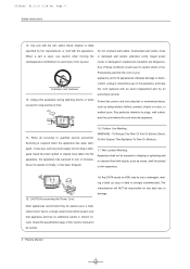
... your appliance, and if its appearance indicates damage or deteri- Wet Location Marking : Apparatus shall not be placed on HDD may be certain. 4 Plasma Monitor Overloaded wall outlets, loose When a cart is required when the apparatus has been dam- To Reduce The Risk Of Fire Or Electric Shock,... Do Not Expose This Appliance To Rain Or Moisture. Use only with the cart, stand, tripod, bracket, or table specified by an authorized servicer. 13. Unplug this owner's manual to rain or moisture, does not operate normally, ...
... your appliance, and if its appearance indicates damage or deteri- Wet Location Marking : Apparatus shall not be placed on HDD may be certain. 4 Plasma Monitor Overloaded wall outlets, loose When a cart is required when the apparatus has been dam- To Reduce The Risk Of Fire Or Electric Shock,... Do Not Expose This Appliance To Rain Or Moisture. Use only with the cart, stand, tripod, bracket, or table specified by an authorized servicer. 13. Unplug this owner's manual to rain or moisture, does not operate normally, ...
Owners Manual
Page 8
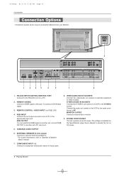
... of external equipment to these sockets. COMPONENT INPUT 1-2 Connect a component video/audio device to these jacks. 8 Plasma Monitor HDMI/DVI (VIDEO) Connect a HDMI signal to 'Speaker & Speaker Stand' manual. 7. RGB OUTPUT You can watch the RGB signal on another set, connect RGB OUTPUT to the S-VIDEO... socket. Connect the audio out sockets of an VCR to another set on an AC power. Connection panels shown may be somewhat different from a...
... of external equipment to these sockets. COMPONENT INPUT 1-2 Connect a component video/audio device to these jacks. 8 Plasma Monitor HDMI/DVI (VIDEO) Connect a HDMI signal to 'Speaker & Speaker Stand' manual. 7. RGB OUTPUT You can watch the RGB signal on another set, connect RGB OUTPUT to the S-VIDEO... socket. Connect the audio out sockets of an VCR to another set on an AC power. Connection panels shown may be somewhat different from a...
Owners Manual
Page 10
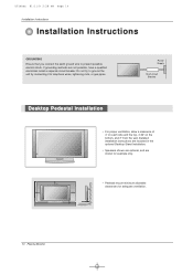
If grounding methods are shown for example only. • Pedestal mount minimum allowable clearances for adequate ventilation. 10 Plasma Monitor Power Supply Short-circuit Breaker Desktop Pedestal Installation • For proper ventilation, allow a clearance of 4" on each side and ...the top, 2.36" on the bottom, and 2" from the wall. Detailed installation instructions are included in the optional Desktop Stand Installation. • Speakers shown are optional, and are not possible, have a qualified electrician install a separate circuit breaker. U514Aen 81/11/9 2:28 PM...
If grounding methods are shown for example only. • Pedestal mount minimum allowable clearances for adequate ventilation. 10 Plasma Monitor Power Supply Short-circuit Breaker Desktop Pedestal Installation • For proper ventilation, allow a clearance of 4" on each side and ...the top, 2.36" on the bottom, and 2" from the wall. Detailed installation instructions are included in the optional Desktop Stand Installation. • Speakers shown are optional, and are not possible, have a qualified electrician install a separate circuit breaker. U514Aen 81/11/9 2:28 PM...

Service Manual
Page 7
LG TV AS mark Owner's Manual Power Cord MUTE POWER INPUT MULTIMEDIA I/II LIST/ ARC MENU OK VOL VOL 123 456 789 PSM 0 SSM SPLIT ZOOM ... can be added. - Contract your dealer for quality improvement without any notification new optional extras can be changed or modified for buying these items. 40 42 40 42 50 50 42 40 40 42 50 Tilt wall mounting bracket Desktop stand Ceiling mounting bracket Speakers Video cables -7-
LG TV AS mark Owner's Manual Power Cord MUTE POWER INPUT MULTIMEDIA I/II LIST/ ARC MENU OK VOL VOL 123 456 789 PSM 0 SSM SPLIT ZOOM ... can be added. - Contract your dealer for quality improvement without any notification new optional extras can be changed or modified for buying these items. 40 42 40 42 50 50 42 40 40 42 50 Tilt wall mounting bracket Desktop stand Ceiling mounting bracket Speakers Video cables -7-

Service Manual
Page 10
...than 20 minutes, (Especially digital pattern, cross hatch pattern) after image may be operated prior to check PANEL. ADJUSTMENT INSTRUCTIONS 1. However, the use an isolation transformer. Setting up the LGIDS 1) Install the LGIDS... be performed in Communication dialog. (If your PC. 3) Extract [files.zip] to Stand-by 'PASS' at [NVRAM File]. 4) Click the [Download] button. Specification (1) Because this mode. ...[ Single color pattern(RED/BLUE/GREEN) of the 42" PDP TV, RF-052A Chassis. 2. And check your connection in the circumstance of 25...
...than 20 minutes, (Especially digital pattern, cross hatch pattern) after image may be operated prior to check PANEL. ADJUSTMENT INSTRUCTIONS 1. However, the use an isolation transformer. Setting up the LGIDS 1) Install the LGIDS... be performed in Communication dialog. (If your PC. 3) Extract [files.zip] to Stand-by 'PASS' at [NVRAM File]. 4) Click the [Download] button. Specification (1) Because this mode. ...[ Single color pattern(RED/BLUE/GREEN) of the 42" PDP TV, RF-052A Chassis. 2. And check your connection in the circumstance of 25...

Service Manual
Page 19
... case of Z- operation: Replace VSC Board After crisis COF of Ctrl-B/D? Yes Is the Z-Board No normal? Is output the normality Low/High voltage except Stand-by 5V? Is the output voltage Is the Fuse(FS2) on Z-B/D Is the output voltage Yes normal after remove Yes normal? (In case of Y-B/D? After...
... case of Z- operation: Replace VSC Board After crisis COF of Ctrl-B/D? Yes Is the Z-Board No normal? Is output the normality Low/High voltage except Stand-by 5V? Is the output voltage Is the Fuse(FS2) on Z-B/D Is the output voltage Yes normal after remove Yes normal? (In case of Y-B/D? After...

Service Manual
Page 20
... X-Board. Yes Is the No VSC Board normal? Yes normal after Yes remove P1, 2, 4, 9, 10 connector of Z-B/D? Is output the normality Low/High voltage except Stand-by 5V? Board normal? After connecting well each board, check the normality operates. Replace Y-Board. Replace Z-Board. If in case normality operates, correspondence COF Fail...
... X-Board. Yes Is the No VSC Board normal? Yes normal after Yes remove P1, 2, 4, 9, 10 connector of Z-B/D? Is output the normality Low/High voltage except Stand-by 5V? Board normal? After connecting well each board, check the normality operates. Replace Y-Board. Replace Z-Board. If in case normality operates, correspondence COF Fail...


