Specification (English)
Page 2
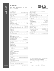
...Component 60p/30p/24p - LCD TV 42LH40 42" Full HD 1080p 120Hz LCD TV (42.0" diagonal) LGusa.com LCD SPECIFICATION Screen Size (Class) 42" Class (42.0" diagonal) Native Display Resolution... no video is a registered trademark of their respective owners. 09/11/09 LG Electronics U.S.A., Inc. 1000 Sylvan Avenue Englewood Cliffs, NJ 07632 Customer Service and...RS-232c In (Control/Service) 1 CABINET/ACCESSORIES Cabinet Color Glossy Black Swivel Stand (degrees) 20º / 20º VESA® Compliant (WxH) 200mm x200mm Remote Control Type Unified POWER Voltage...
...Component 60p/30p/24p - LCD TV 42LH40 42" Full HD 1080p 120Hz LCD TV (42.0" diagonal) LGusa.com LCD SPECIFICATION Screen Size (Class) 42" Class (42.0" diagonal) Native Display Resolution... no video is a registered trademark of their respective owners. 09/11/09 LG Electronics U.S.A., Inc. 1000 Sylvan Avenue Englewood Cliffs, NJ 07632 Customer Service and...RS-232c In (Control/Service) 1 CABINET/ACCESSORIES Cabinet Color Glossy Black Swivel Stand (degrees) 20º / 20º VESA® Compliant (WxH) 200mm x200mm Remote Control Type Unified POWER Voltage...

Owner's Manual (English)
Page 6
... Setup 25 DVD Setup 28 VCR Setup 30 Other A/V Source Setup 32 PC Setup 33 USB Connection 40 Audio out Connection 41 WATCHING TV / CHANNEL CONTROL Remote Control Functions 42 Turning On TV 44 Channel Selection 44 Volume Adjustment 44 Initial Setting 45 On-Screen Menus Selection 46 Quick Menu 47 6 Channel Setup - User Mode 73...
... Setup 25 DVD Setup 28 VCR Setup 30 Other A/V Source Setup 32 PC Setup 33 USB Connection 40 Audio out Connection 41 WATCHING TV / CHANNEL CONTROL Remote Control Functions 42 Turning On TV 44 Channel Selection 44 Volume Adjustment 44 Initial Setting 45 On-Screen Menus Selection 46 Quick Menu 47 6 Channel Setup - User Mode 73...

Owner's Manual (English)
Page 9
...55LH41, 47/55LH55) x 4 Bolts for stand assembly Screw for stand fixing (Refer to P.16) (Refer to P.22) Protection Cover For 32/42/47CL40 (Except 47CL40) (Except 47CL40) x 4 x 4 Bolts for stand assembly Screw for stand fixing (Refer to P.14) (Refer to ...missing, please contact the dealer where you purchased the TV. MESNLUEEPRATIO MENU POWER ENERGYINSAVPINUG T RETURN INFO ENTER VOL FAMVARK AV MODE 1 4 MUTE 2 CH P A G E 7 5 3 8 6 LIST 0 9 FLASHBK 1.5V 1.5V Owner's Manual CD Manual Remote Control, Batteries Power Cord Not included with all models Polishing ...
...55LH41, 47/55LH55) x 4 Bolts for stand assembly Screw for stand fixing (Refer to P.16) (Refer to P.22) Protection Cover For 32/42/47CL40 (Except 47CL40) (Except 47CL40) x 4 x 4 Bolts for stand assembly Screw for stand fixing (Refer to P.14) (Refer to ...missing, please contact the dealer where you purchased the TV. MESNLUEEPRATIO MENU POWER ENERGYINSAVPINUG T RETURN INFO ENTER VOL FAMVARK AV MODE 1 4 MUTE 2 CH P A G E 7 5 3 8 6 LIST 0 9 FLASHBK 1.5V 1.5V Owner's Manual CD Manual Remote Control, Batteries Power Cord Not included with all models Polishing ...

Owner's Manual (English)
Page 10
G p.80) CH VOL ENTER MENU INPUT CHANNEL (D,E) Buttons VOLUME (+, -) Buttons ENTER Button MENU Button INPUT Button POWER Button OFF ON AC power control switch 10 PREPARATION PREPARATION FRONT PANEL INFORMATION I Image shown may differ from your TV. 32/37/42/47/55LH40, 32/37/42/47/55LH41, 37/42/47/55LH55 SPEAKER Remote Control Sensor, Intelligent Sensor Adjusts picture according to the surrounding conditions Power/Standby Indicator Illuminates red in the OPTION menu. Illuminates blue when the TV is switched on. (Can be adjusted Power Indicator in standby mode.
G p.80) CH VOL ENTER MENU INPUT CHANNEL (D,E) Buttons VOLUME (+, -) Buttons ENTER Button MENU Button INPUT Button POWER Button OFF ON AC power control switch 10 PREPARATION PREPARATION FRONT PANEL INFORMATION I Image shown may differ from your TV. 32/37/42/47/55LH40, 32/37/42/47/55LH41, 37/42/47/55LH55 SPEAKER Remote Control Sensor, Intelligent Sensor Adjusts picture according to the surrounding conditions Power/Standby Indicator Illuminates red in the OPTION menu. Illuminates blue when the TV is switched on. (Can be adjusted Power Indicator in standby mode.
Owner's Manual (English)
Page 11
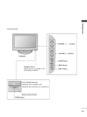
Illuminates blue when the set is switched on. Remote Control Sensor POWER Button 11 PREPARATION 32/42/47CL40 CH CHANNEL ( , ) Buttons SPEAKER Intelligent Sensor Adjusts picture according to the surrounding conditions VOL ENTER MENU INPUT VOLUME (+, -) Buttons ENTER Button MENU Button INPUT Button Power/Standby Indicator Illuminates red in standby mode.
Illuminates blue when the set is switched on. Remote Control Sensor POWER Button 11 PREPARATION 32/42/47CL40 CH CHANNEL ( , ) Buttons SPEAKER Intelligent Sensor Adjusts picture according to the surrounding conditions VOL ENTER MENU INPUT VOLUME (+, -) Buttons ENTER Button MENU Button INPUT Button Power/Standby Indicator Illuminates red in standby mode.

Owner's Manual (English)
Page 25
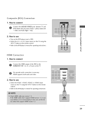
...the COMPONENT IN VIDEO 1 jacks on the TV. 2. Component Connection 1. Y PB PR L R EXTERNAL EQUIPMENT SETUP Connect the audio output of the digital settop box to COMPONENT IN 2 input, select the Component2 input source on the remote control. How to connect 1 Connect the video ...outputs (Y, PB, PR) of the digital set -top box operation.) I Select the Component1 input source on the TV using the INPUT button on the TV. 1 2 AV IN 1 VIDEO L(MONO) AUDIO R 3 ...
...the COMPONENT IN VIDEO 1 jacks on the TV. 2. Component Connection 1. Y PB PR L R EXTERNAL EQUIPMENT SETUP Connect the audio output of the digital settop box to COMPONENT IN 2 input, select the Component2 input source on the remote control. How to connect 1 Connect the video ...outputs (Y, PB, PR) of the digital set -top box operation.) I Select the Component1 input source on the TV using the INPUT button on the TV. 1 2 AV IN 1 VIDEO L(MONO) AUDIO R 3 ...

Owner's Manual (English)
Page 26
...MONO) AUDIO R 3 2 L R 1 EO AUDIO OMPONENT IN /DVI IN RGB IN (PC) AUDIO IN O (RGB/DVI) A RS-232C IN C (CONTROL&SERVICE) 1 ! NOTE G Check HDMI cable over version 1.3. HDMI OUTPUT ( ) HDMI-DTV Resolution Horizontal Vertical Frequency(KHz) Frequency(Hz) 720x480p 1280x720p 1920x1080i 1920x1080p 31... box. (Refer to HDMI/DVI IN 1, 2, 3, or 4 jack on the remote control. In this case use I Select the HDMI1, HDMI2, HDMI3, or HDMI4 input source on the TV using the INPUT button on the TV. 2 No separate audio connection is necessary. EXTERNAL EQUIPMENT SETUP ( ) HDMI Connection...
...MONO) AUDIO R 3 2 L R 1 EO AUDIO OMPONENT IN /DVI IN RGB IN (PC) AUDIO IN O (RGB/DVI) A RS-232C IN C (CONTROL&SERVICE) 1 ! NOTE G Check HDMI cable over version 1.3. HDMI OUTPUT ( ) HDMI-DTV Resolution Horizontal Vertical Frequency(KHz) Frequency(Hz) 720x480p 1280x720p 1920x1080i 1920x1080p 31... box. (Refer to HDMI/DVI IN 1, 2, 3, or 4 jack on the remote control. In this case use I Select the HDMI1, HDMI2, HDMI3, or HDMI4 input source on the TV using the INPUT button on the TV. 2 No separate audio connection is necessary. EXTERNAL EQUIPMENT SETUP ( ) HDMI Connection...

Owner's Manual (English)
Page 27
... to the HDMI/DVI IN 1, 2, or 3 jack on the remote control. DVI doesn't support audio, so a separate audio connection is required for the digital set-top box.) I Select the HDMI1, HDMI2, or HDMI3 input source on the TV using the INPUT button on the TV. 2 Connect the digital set -top box. (Refer to HDMI...
... to the HDMI/DVI IN 1, 2, or 3 jack on the remote control. DVI doesn't support audio, so a separate audio connection is required for the digital set-top box.) I Select the HDMI1, HDMI2, or HDMI3 input source on the TV using the INPUT button on the TV. 2 Connect the digital set -top box. (Refer to HDMI...
Owner's Manual (English)
Page 28
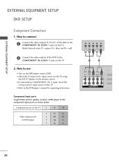
... input source on the DVD player, insert a DVD. I If connected to use I Refer to the COMPONENT IN VIDEO 1 jacks on the TV. 2. I Turn on the TV. How to connect 1 Connect the video outputs (Y, PB, PR) of the DVD to the component input ports as shown below. Match the ..., and PR = red). 2 Connect the audio outputs of the DVD to the DVD player's manual for operating instructions. Component ports on the TV Y PB PR Video output ports on the remote control. Component Input ports To get better picture quality, connect a DVD player to the COMPONENT IN AUDIO 1 jacks on the...
... input source on the DVD player, insert a DVD. I If connected to use I Refer to the COMPONENT IN VIDEO 1 jacks on the TV. 2. I Turn on the TV. How to connect 1 Connect the video outputs (Y, PB, PR) of the DVD to the component input ports as shown below. Match the ..., and PR = red). 2 Connect the audio outputs of the DVD to the DVD player's manual for operating instructions. Component ports on the TV Y PB PR Video output ports on the remote control. Component Input ports To get better picture quality, connect a DVD player to the COMPONENT IN AUDIO 1 jacks on the...
Owner's Manual (English)
Page 29
... I Select the HDMI1, HDMI2, HDMI3, or HDMI4 input source on the TV using the INPUT button on the TV. 2 No separate audio connection is necessary. How to the DVD player's manual for operating instructions. I Turn on the remote control. HDMI Connection 1. In this case use I Refer to use I Select the... A V 1 or A V 2 input source on the TV using the INPUT button on the DVD player, insert a DVD. NOTE G Check...
... I Select the HDMI1, HDMI2, HDMI3, or HDMI4 input source on the TV using the INPUT button on the TV. 2 No separate audio connection is necessary. How to the DVD player's manual for operating instructions. I Turn on the remote control. HDMI Connection 1. In this case use I Refer to use I Select the... A V 1 or A V 2 input source on the TV using the INPUT button on the DVD player, insert a DVD. NOTE G Check...

Owner's Manual (English)
Page 31
... G If you have a mono VCR, connect the audio cable from the VCR to connect 1 Connect the AUDIO/VIDEO jacks between TV and VCR. How to the AUDIO L/MONO jack of the TV. AV IN 1 /DVI VIDEO L(MONO) AUDIO R 3 2 2 L R 1 1 VIDEO AUDIO COMPONENT IN 1 ANT IN S-VIDEO VIDEO L R AUDIO ANT OUT OUTPUT ... press PLAY on the VCR. (Refer to the VCR owner's manual.) I If connected to AV IN 2, select AV2 input source on the remote control. EXTERNAL EQUIPMENT SETUP Composite (RCA) Connection 1. Match the jack colors (Video = yellow, Audio Left = white, and Audio Right = red) 2.
... G If you have a mono VCR, connect the audio cable from the VCR to connect 1 Connect the AUDIO/VIDEO jacks between TV and VCR. How to the AUDIO L/MONO jack of the TV. AV IN 1 /DVI VIDEO L(MONO) AUDIO R 3 2 2 L R 1 1 VIDEO AUDIO COMPONENT IN 1 ANT IN S-VIDEO VIDEO L R AUDIO ANT OUT OUTPUT ... press PLAY on the VCR. (Refer to the VCR owner's manual.) I If connected to AV IN 2, select AV2 input source on the remote control. EXTERNAL EQUIPMENT SETUP Composite (RCA) Connection 1. Match the jack colors (Video = yellow, Audio Left = white, and Audio Right = red) 2.
Owner's Manual (English)
Page 32
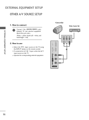
EXTERNAL EQUIPMENT SETUP EXTERNAL EQUIPMENT SETUP OTHER A/V SOURCE SETUP 1. USB IN IN 4 Camcorder Video Game Set VIDEO L R 1 VIDEO L/MONO AUDIO R AV IN 2 32 Match the jack colors. (Video = yellow, Audio Left = white, and Audio Right = red) 2. I If connected to AV IN 1 input, select the A V 1 input source on the remote control. I Select the A V 2 input source on the TV using the INPUT button on the TV. How to connect 1 Connect the AUDIO/VIDEO jacks between TV and external equipment. How to use I Operate the corresponding external equipment.
EXTERNAL EQUIPMENT SETUP EXTERNAL EQUIPMENT SETUP OTHER A/V SOURCE SETUP 1. USB IN IN 4 Camcorder Video Game Set VIDEO L R 1 VIDEO L/MONO AUDIO R AV IN 2 32 Match the jack colors. (Video = yellow, Audio Left = white, and Audio Right = red) 2. I If connected to AV IN 1 input, select the A V 1 input source on the remote control. I Select the A V 2 input source on the TV using the INPUT button on the TV. How to connect 1 Connect the AUDIO/VIDEO jacks between TV and external equipment. How to use I Operate the corresponding external equipment.
Owner's Manual (English)
Page 33
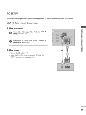
... (RGB/DVI) OPTICAL DIGITAL AUDIO OUT ANTENNA/ RS-232C IN CABLE IN (CONTROL&SERVICE) 2. EXTERNAL EQUIPMENT SETUP PC SETUP This TV provides Plug and Play capability, meaning that the PC adjusts automatically to use I Select the RGB-PC input source on the TV using the INPUT button on the remote control. 2 1 AUDIO RGB OUTPUT ( ) 33
... (RGB/DVI) OPTICAL DIGITAL AUDIO OUT ANTENNA/ RS-232C IN CABLE IN (CONTROL&SERVICE) 2. EXTERNAL EQUIPMENT SETUP PC SETUP This TV provides Plug and Play capability, meaning that the PC adjusts automatically to use I Select the RGB-PC input source on the TV using the INPUT button on the remote control. 2 1 AUDIO RGB OUTPUT ( ) 33

Owner's Manual (English)
Page 34
... OUTPUT AUDIO 34 EXTERNAL EQUIPMENT SETUP EXTERNAL EQUIPMENT SETUP DVI to use the latest cables that support HDMI version 1.3. I Turn on the PC and the TV. If the HDMI cables don't support HDMI version 1.3, it can cause flickers or no screen display. AV IN 1 VIDEO L(MONO) AUDIO R 3 2 L R 1 O AUDIO MPONENT ...connect 1 Connect the DVI output of the PC to the HDMI/DVI IN 1, 2, or 3 jack on the TV. 2 Connect the PC audio output to the AUDIO IN (RGB/DVI) jack on the remote control. How to HDMI Connection 1. In this case use I Select the HDMI1, HDMI2, or HDMI3 input source on the...
... OUTPUT AUDIO 34 EXTERNAL EQUIPMENT SETUP EXTERNAL EQUIPMENT SETUP DVI to use the latest cables that support HDMI version 1.3. I Turn on the PC and the TV. If the HDMI cables don't support HDMI version 1.3, it can cause flickers or no screen display. AV IN 1 VIDEO L(MONO) AUDIO R 3 2 L R 1 O AUDIO MPONENT ...connect 1 Connect the DVI output of the PC to the HDMI/DVI IN 1, 2, or 3 jack on the TV. 2 Connect the PC audio output to the AUDIO IN (RGB/DVI) jack on the remote control. How to HDMI Connection 1. In this case use I Select the HDMI1, HDMI2, or HDMI3 input source on the...

Owner's Manual (English)
Page 42
... INPUT ENERGY SAVING SLEEP Q. G p.98 POWER Turns the TV on the TV. When you toggle this button, the SIMPLINK menu appears at the remote control sensor on from standby. MENU MENU ENTER RETURN INFO AV MODE VOL MARK FAV P CH A G E MUTE 123 456 789 0 FLASHBK LIST 42 G p.68 SLEEP Select the amount of Quick Menu...
... INPUT ENERGY SAVING SLEEP Q. G p.98 POWER Turns the TV on the TV. When you toggle this button, the SIMPLINK menu appears at the remote control sensor on from standby. MENU MENU ENTER RETURN INFO AV MODE VOL MARK FAV P CH A G E MUTE 123 456 789 0 FLASHBK LIST 42 G p.68 SLEEP Select the amount of Quick Menu...

Owner's Manual (English)
Page 44
... to remember which power state it will appear whenever the TV is switched on the TV, reset the Clock function. I This TV is programmed to be away on TV (Except 32/42/47CL40). At this moment, the TV switches to standby mode. ! WATCHING TV / CHANNEL CONTROL CHANNEL SELECTION 1 Press the CH ( or ) or... on until the Initial setting procedure is unplugged once or turn TV on, press the , INPUT, CH (DE or ) button on the TV or press the POWER, INPUT, CH ( or ), Number (0~9) button on the remote control. 2 Select the viewing source by pressing the MUTE or VOL (+ or -) button. 44 G ...
... to remember which power state it will appear whenever the TV is switched on the TV, reset the Clock function. I This TV is programmed to be away on TV (Except 32/42/47CL40). At this moment, the TV switches to standby mode. ! WATCHING TV / CHANNEL CONTROL CHANNEL SELECTION 1 Press the CH ( or ) or... on until the Initial setting procedure is unplugged once or turn TV on, press the , INPUT, CH (DE or ) button on the TV or press the POWER, INPUT, CH ( or ), Number (0~9) button on the remote control. 2 Select the viewing source by pressing the MUTE or VOL (+ or -) button. 44 G ...

Owner's Manual (English)
Page 57
...E 1 MENU Select OPTION. 2 ENTER Select Key Lock. 3 ENTER Select O n or O f f. 4 RETURN Return to TV viewing. MENU Return to the previous menu. Key Lock' appears on the screen if any button on the remote control. This TV is programmed to remember which option it can only be used to prevent unauthorized viewing by...Caption Set ID E : English : English : On : On Off On : Off : 1 I In Key Lock 'O n', if the TV is turned off . This feature can be used with the remote control. WATCHING TV / CHANNEL CONTROL KEY LOCK The TV can be set up so that it was last set to even if you turn the...
...E 1 MENU Select OPTION. 2 ENTER Select Key Lock. 3 ENTER Select O n or O f f. 4 RETURN Return to TV viewing. MENU Return to the previous menu. Key Lock' appears on the screen if any button on the remote control. This TV is programmed to remember which option it can only be used to prevent unauthorized viewing by...Caption Set ID E : English : English : On : On Off On : Off : 1 I In Key Lock 'O n', if the TV is turned off . This feature can be used with the remote control. WATCHING TV / CHANNEL CONTROL KEY LOCK The TV can be set up so that it was last set to even if you turn the...
Owner's Manual (English)
Page 58
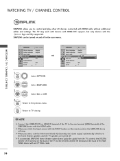
...: 1 E ! G When you switch the Input source with HDMI cable without additional cables and settings. SIMPLINK can be turned on and off . WATCHING TV / CHANNEL CONTROL OPTION Menu Language Audio Language Input Label SIMPLINK Key Lock Simple Manual Caption Set ID E Move Enter : English : English : On : Off : Off :...This TV may work with devices with HDMI-CEC support, but only devices with the HDMI cable. G When you select a device with an OPTICAL cable. 58 G If a connected SIMPLINK home theater system doesn't play other AV devices connected with the INPUT button on the remote control,...
...: 1 E ! G When you switch the Input source with HDMI cable without additional cables and settings. SIMPLINK can be turned on and off . WATCHING TV / CHANNEL CONTROL OPTION Menu Language Audio Language Input Label SIMPLINK Key Lock Simple Manual Caption Set ID E Move Enter : English : English : On : Off : Off :...This TV may work with devices with HDMI-CEC support, but only devices with the HDMI cable. G When you select a device with an OPTICAL cable. 58 G If a connected SIMPLINK home theater system doesn't play other AV devices connected with the INPUT button on the remote control,...
Owner's Manual (English)
Page 61
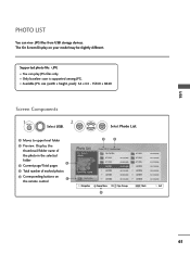
... folder 2 3 Current page/Total pages 4 Total number of marked photos 5 Corresponding buttons on your model may be slightly different. The On Screen Display on 1 the remote control 3 4 Photo List Drive1 JMJ001 1366x768, 125KB Up Folder Page 2/3 No Marked Up Folder KY101 06/10/2008 KY102 04/03/2008 JMJ001 01/01/2000...
... folder 2 3 Current page/Total pages 4 Total number of marked photos 5 Corresponding buttons on your model may be slightly different. The On Screen Display on 1 the remote control 3 4 Photo List Drive1 JMJ001 1366x768, 125KB Up Folder Page 2/3 No Marked Up Folder KY101 06/10/2008 KY102 04/03/2008 JMJ001 01/01/2000...
Owner's Manual (English)
Page 65
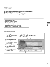
The On Screen Display on 1 the remote control Music List Drive1 3 4 Page 2/3 No Marked Title Up Folder A 00:00 / 04:16 Up Folder Navigation Popup Menu CH Page Change 5 Duration MARK Mark Exit ..., 24 kHz MPEG2.5 layer 3: 8 kHz, 11.025 kHz, 12 kHz Screen Components 1 MENU Select U S B. 2 ENTER ENTER Select M u s i c L i s t. 1 Moves to play back copy-protected files. This TV cannot play MP3 files from a USB storage device. USB MUSIC LIST You can use the Music List menu to upper level folder 2 Preview: If any...
The On Screen Display on 1 the remote control Music List Drive1 3 4 Page 2/3 No Marked Title Up Folder A 00:00 / 04:16 Up Folder Navigation Popup Menu CH Page Change 5 Duration MARK Mark Exit ..., 24 kHz MPEG2.5 layer 3: 8 kHz, 11.025 kHz, 12 kHz Screen Components 1 MENU Select U S B. 2 ENTER ENTER Select M u s i c L i s t. 1 Moves to play back copy-protected files. This TV cannot play MP3 files from a USB storage device. USB MUSIC LIST You can use the Music List menu to upper level folder 2 Preview: If any...

