Owner's Manual
Page 1
P/NO : MFL34797015 (0705-REV00) Printed in Korea www.lge.com Record model number and serial number of the set . LCD TV OWNER'S MANUAL LCD TV MODELS 15LS1RA 20LS1RA Please read this information to your set . See the label attached on the back cover and quote this manual carefully before operating your dealer when you require service. Retain it for future reference.
P/NO : MFL34797015 (0705-REV00) Printed in Korea www.lge.com Record model number and serial number of the set . LCD TV OWNER'S MANUAL LCD TV MODELS 15LS1RA 20LS1RA Please read this information to your set . See the label attached on the back cover and quote this manual carefully before operating your dealer when you require service. Retain it for future reference.
Owner's Manual
Page 5
...when it to protect a child from eating them. This is normal, there is turned on the screen, appearing as diagonal length of this product with TV. Avoid touching the LCD screen or holding the speakers. Doing so may produce some temporary distortion effects on the monitor's performance. This may cause a ...damaged the product or could give an electric shock. 17 Do not allow a impact shock or any hot objects like a heater. NOTE G If the TV feels cold to fall , causing serious injury to a child or adult, and serious damage to clean the internal part of time. Some minute dot ...
...when it to protect a child from eating them. This is normal, there is turned on the screen, appearing as diagonal length of this product with TV. Avoid touching the LCD screen or holding the speakers. Doing so may produce some temporary distortion effects on the monitor's performance. This may cause a ...damaged the product or could give an electric shock. 17 Do not allow a impact shock or any hot objects like a heater. NOTE G If the TV feels cold to fall , causing serious injury to a child or adult, and serious damage to clean the internal part of time. Some minute dot ...
Owner's Manual
Page 6
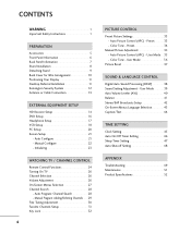
... 31 Key Lock 32 4 PICTURE CONTROL Preset Picture Settings 33 - Color Tone - Auto Configure 21 Manual Configure 22 Initializing 23 WATCHING TV / CHANNEL CONTROL Remote Control Functions 24 Turning On TV 26 Channel Selection 26 Volume Adjustment 26 On-Screen Menus Selection 27 Channel Search 28 - Auto Picture Control (APC) - Auto Picture...
... 31 Key Lock 32 4 PICTURE CONTROL Preset Picture Settings 33 - Color Tone - Auto Configure 21 Manual Configure 22 Initializing 23 WATCHING TV / CHANNEL CONTROL Remote Control Functions 24 Turning On TV 26 Channel Selection 26 Volume Adjustment 26 On-Screen Menus Selection 27 Channel Search 28 - Auto Picture Control (APC) - Auto Picture...
Owner's Manual
Page 7
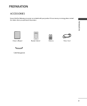
Owner's Manual Owner's Manual POWER TV INPUT MTS A.PROG MEMORY/ERASE CAPTION 1 2 3 4 56 7 8 9 0 MUTE FCR CH Remote Control 1.5V 1.5V Batteries Power Cord Cable Management 5 PREPARATION PREPARATION ACCESSORIES Ensure that the following accessories are included with your product. If an accessory is missing, please contact the dealer where you purchased the product.
Owner's Manual Owner's Manual POWER TV INPUT MTS A.PROG MEMORY/ERASE CAPTION 1 2 3 4 56 7 8 9 0 MUTE FCR CH Remote Control 1.5V 1.5V Batteries Power Cord Cable Management 5 PREPARATION PREPARATION ACCESSORIES Ensure that the following accessories are included with your product. If an accessory is missing, please contact the dealer where you purchased the product.
Owner's Manual
Page 8
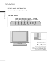
PREPARATION PREPARATION FRONT PANEL INFORMATION I INPUT MENU ENTER VOL CH Remote Control Sensor Power Standby Indicator Illuminates red in standby mode. Front Panel Controls POWER INPUT MENU ENTER VOLUME CHANNEL Button Button Button Button (F,G)Buttons (E,D)Buttons /I Here shown may be somewhat different from your TV. When the TV is turned on, the indicator blinks green and then illuminates green before the picture is displayed. 6
PREPARATION PREPARATION FRONT PANEL INFORMATION I INPUT MENU ENTER VOL CH Remote Control Sensor Power Standby Indicator Illuminates red in standby mode. Front Panel Controls POWER INPUT MENU ENTER VOLUME CHANNEL Button Button Button Button (F,G)Buttons (E,D)Buttons /I Here shown may be somewhat different from your TV. When the TV is turned on, the indicator blinks green and then illuminates green before the picture is displayed. 6
Owner's Manual
Page 9
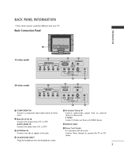
... IN (480i/480p) VIDEO AUDIO 6 SERVICE ONLY 3 ANTENNA IN ( ) VIDEO AUDIO S-VIDEO H/P (MONO) AV IN ( ) 5 4 1 COMPONENT IN Connect a component video/audio device to operate the TV on DC power. 7 S-VIDEO Connect S-Video out from your...
... IN (480i/480p) VIDEO AUDIO 6 SERVICE ONLY 3 ANTENNA IN ( ) VIDEO AUDIO S-VIDEO H/P (MONO) AV IN ( ) 5 4 1 COMPONENT IN Connect a component video/audio device to operate the TV on DC power. 7 S-VIDEO Connect S-Video out from your...
Owner's Manual
Page 10
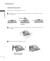
Insert the stand body into a cover base until clicking sound. Make sure that will protect product and screen from your TV. 1 Assemble parts of the stand body with cover base of the stand. stand body cover base 2 Carefully place the product screen side down on a cushioned surface that the stand body is bent upward. 8 PREPARATION PREPARATION STAND INSTALLATION I Here shown may be somewhat different from damage. 3 Place the product stand on the product as shown.
Insert the stand body into a cover base until clicking sound. Make sure that will protect product and screen from your TV. 1 Assemble parts of the stand body with cover base of the stand. stand body cover base 2 Carefully place the product screen side down on a cushioned surface that the stand body is bent upward. 8 PREPARATION PREPARATION STAND INSTALLATION I Here shown may be somewhat different from damage. 3 Place the product stand on the product as shown.
Owner's Manual
Page 11
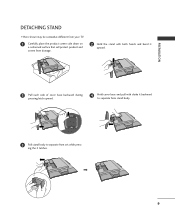
ing the 2 latches. 9 PREPARATION DETACHING STAND I Here shown may be somewhat different from your TV. 1 Carefully place the product screen side down on a cushioned surface that will protect product and screen from damage. 2 Hold the stand with both hands and bend it upward. 3 Pull each side of cover base backward during pressing latch upward. 4 Hold cover base and pull with shake it backward to separate from stand body. 5 Pull stand body to separate from set while press-
ing the 2 latches. 9 PREPARATION DETACHING STAND I Here shown may be somewhat different from your TV. 1 Carefully place the product screen side down on a cushioned surface that will protect product and screen from damage. 2 Hold the stand with both hands and bend it upward. 3 Pull each side of cover base backward during pressing latch upward. 4 Hold cover base and pull with shake it backward to separate from stand body. 5 Pull stand body to separate from set while press-
Owner's Manual
Page 12
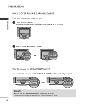
PREPARATION PREPARATION BACK COVER FOR WIRE ARRANGEMENT I Here shown may be somewhat different from your TV. 1 Connect the cables as shown. Hold the CABLE MANAGEMENT with both hands and pull it upward. ! NOTE G Do not hold the CABLE MANAGEMENT when moving the product. - To connect an additional equipment, see the EXTERNAL EQUIPMENT SETUP section. 2 Install the CABLE MANAGEMENT as necessary. How to remove the CABLE MANAGEMENT First, press the cable management. If the product is dropped, you may be injured or the product may be broken. 10
PREPARATION PREPARATION BACK COVER FOR WIRE ARRANGEMENT I Here shown may be somewhat different from your TV. 1 Connect the cables as shown. Hold the CABLE MANAGEMENT with both hands and pull it upward. ! NOTE G Do not hold the CABLE MANAGEMENT when moving the product. - To connect an additional equipment, see the EXTERNAL EQUIPMENT SETUP section. 2 Install the CABLE MANAGEMENT as necessary. How to remove the CABLE MANAGEMENT First, press the cable management. If the product is dropped, you may be injured or the product may be broken. 10
Owner's Manual
Page 13
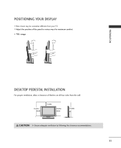
I Here shown may be somewhat different from the wall. 4 inches 4 inches 4 inches R 4 inches CAUTION G Ensure adequate ventilation by following the clearance recommendations. 11 PREPARATION POSITIONING YOUR DISPLAY I Adjust the position of the panel in various ways for maximum comfort. • Tilt range 12~10 03 DESKTOP PEDESTAL INSTALLATION For proper ventilation, allow a clearance of 4inches on all four sides from your TV.
I Here shown may be somewhat different from the wall. 4 inches 4 inches 4 inches R 4 inches CAUTION G Ensure adequate ventilation by following the clearance recommendations. 11 PREPARATION POSITIONING YOUR DISPLAY I Adjust the position of the panel in various ways for maximum comfort. • Tilt range 12~10 03 DESKTOP PEDESTAL INSTALLATION For proper ventilation, allow a clearance of 4inches on all four sides from your TV.
Owner's Manual
Page 14
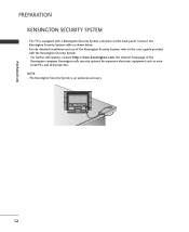
... the Kensington Security System, refer to the user's guide provided with a Kensington Security System connector on the back panel. PREPARATION PREPARATION KENSINGTON SECURITY SYSTEM - The TV is an optional accessory. 12 Kensington sells security systems for expensive electronic equipment such as shown below. -
... the Kensington Security System, refer to the user's guide provided with a Kensington Security System connector on the back panel. PREPARATION PREPARATION KENSINGTON SECURITY SYSTEM - The TV is an optional accessory. 12 Kensington sells security systems for expensive electronic equipment such as shown below. -
Owner's Manual
Page 15
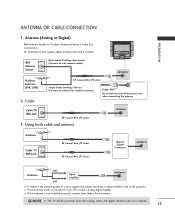
... Jack RF Coaxial Wire (75 ohm) 3. I If the antenna is not installed properly, contact your dealer for two TV's, install a 2-Way Signal S(plit) ter. NOTE G The TV will let you know when the analog, cable, and digital channel scans are complete. 13 PREPARATION ANTENNA OR CABLE CONNECTION...for outdoor antenna) Coppe(r W) ire Be careful not to be split for assistance. ! Using both cable and antenna ANTENNA IN ( ) ( ) Antenna Cable TV Wall Jack RF Coaxial Wire (75 ohm) RF Coaxial Wire (75 ohm) Diplexer (Signal ( ) Combiner) ANTENNA IN ( ) Antenna UHF Signal Amplifier VHF ANTENNA...
... Jack RF Coaxial Wire (75 ohm) 3. I If the antenna is not installed properly, contact your dealer for two TV's, install a 2-Way Signal S(plit) ter. NOTE G The TV will let you know when the analog, cable, and digital channel scans are complete. 13 PREPARATION ANTENNA OR CABLE CONNECTION...for outdoor antenna) Coppe(r W) ire Be careful not to be split for assistance. ! Using both cable and antenna ANTENNA IN ( ) ( ) Antenna Cable TV Wall Jack RF Coaxial Wire (75 ohm) RF Coaxial Wire (75 ohm) Diplexer (Signal ( ) Combiner) ANTENNA IN ( ) Antenna UHF Signal Amplifier VHF ANTENNA...
Owner's Manual
Page 18
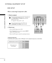
Component ports on the TV Y Y Video output ports Y on the remote control. Match the jack colors (Y = green, PB = blue, and PR = red). COMPONENT IN (480i/480p/720p) VIDEO AUDIO RGB (...
Component ports on the TV Y Y Video output ports Y on the remote control. Match the jack colors (Y = green, PB = blue, and PR = red). COMPONENT IN (480i/480p/720p) VIDEO AUDIO RGB (...
Owner's Manual
Page 20
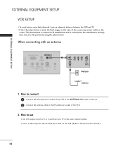
... IN ANT IN 2 OUTPUT SWITCH Wall Jack Antenna 1. How to use I To avoid picture noise (interference), leave an adequate distance between the VCR and TV. I If the 4:3 picture format is common to all manufactures and in socket of the screen may remain visible on the VCR. (Refer to the VCR... owner's manual.) 18 EXTERNAL EQUIPMENT SETUP EXTERNAL EQUIPMENT SETUP VCR SETUP I Set VCR output switch to 3 or 4 and then tune TV to the same channel number. the fixed images on the set. 2 Connect the antenna cable to the RF antenna in consequence the manufactures warranty does...
... IN ANT IN 2 OUTPUT SWITCH Wall Jack Antenna 1. How to use I To avoid picture noise (interference), leave an adequate distance between the VCR and TV. I If the 4:3 picture format is common to all manufactures and in socket of the screen may remain visible on the VCR. (Refer to the VCR... owner's manual.) 18 EXTERNAL EQUIPMENT SETUP EXTERNAL EQUIPMENT SETUP VCR SETUP I Set VCR output switch to 3 or 4 and then tune TV to the same channel number. the fixed images on the set. 2 Connect the antenna cable to the RF antenna in consequence the manufactures warranty does...
Owner's Manual
Page 21
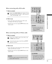
... VCR. (Refer to the S -VIDEO input on the remote control. NOTE G The picture quality is improved: compared to connect 1 Connect the AUDIO/VIDEO jacks between TV and VCR. In the event that you have a mono VCR, connect the audio cable from the VCR to the AUDIO 2 input jacks on the remote...
... VCR. (Refer to the S -VIDEO input on the remote control. NOTE G The picture quality is improved: compared to connect 1 Connect the AUDIO/VIDEO jacks between TV and VCR. In the event that you have a mono VCR, connect the audio cable from the VCR to the AUDIO 2 input jacks on the remote...
Owner's Manual
Page 22
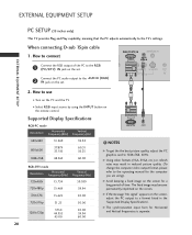
EXTERNAL EQUIPMENT SETUP PC SETUP (15 inches only) This TV provides Plug and Play capability, meaning that the PC adjusts automatically to a format listed in reduced picture quality. (To change the computer video output format, ... R G B (PC/DTV) I Select R G B input source by using ). G If the message "No signal" appears on the PC and the TV. How to the AUDIO (R G B) 2 I Turn on the screen, adjust the PC output to the TV's settings. G The synchronization input form for the computer you are using the INPUT button on the set . Supported...
EXTERNAL EQUIPMENT SETUP PC SETUP (15 inches only) This TV provides Plug and Play capability, meaning that the PC adjusts automatically to a format listed in reduced picture quality. (To change the computer video output format, ... R G B (PC/DTV) I Select R G B input source by using ). G If the message "No signal" appears on the PC and the TV. How to the AUDIO (R G B) 2 I Turn on the screen, adjust the PC output to the TV's settings. G The synchronization input form for the computer you are using the INPUT button on the set . Supported...
Owner's Manual
Page 23
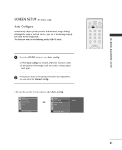
... Auto config.. has finished, O k will be adjusted more after Auto adjustment, you can also use the Screen menu to start DE F G MENU DE F G MENU POWER TV INPUT MTS A.PROG MEMORY/ERASE CAPTION 1 2 3 4 56 7 8 9 0 MUTE FCR CH 21 Manual config. I If the position of the image is functioning properly but needs further...
... Auto config.. has finished, O k will be adjusted more after Auto adjustment, you can also use the Screen menu to start DE F G MENU DE F G MENU POWER TV INPUT MTS A.PROG MEMORY/ERASE CAPTION 1 2 3 4 56 7 8 9 0 MUTE FCR CH 21 Manual config. I If the position of the image is functioning properly but needs further...
Owner's Manual
Page 26
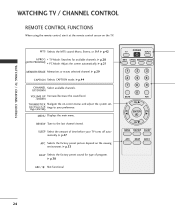
... viewed. G p.28 (AUTO PROGRAM) PC Mode: Adjust the screen automatically. G p.47 APC Selects the factory preset picture depend on the TV. G p.21 MEMORY/ERASE Memorizes or erases selected channel. G p.33 DASP Selects the factory preset sound for available channels. Right/ENTER) MENU... Displays the main menu. G p.44 CHANNEL Select available channels. SLEEP Select the amount of program. REVIEW Tune to your TV turns off automatically. G p.38 * ARC/ Not functional POWER TV INPUT MTS A.PROG MEMORY/ERASE CAPTION 1 2 3 4 56 7 8 9 0 MUTE FCR CH VOL ENTER VOL CH...
... viewed. G p.28 (AUTO PROGRAM) PC Mode: Adjust the screen automatically. G p.47 APC Selects the factory preset picture depend on the TV. G p.21 MEMORY/ERASE Memorizes or erases selected channel. G p.33 DASP Selects the factory preset sound for available channels. Right/ENTER) MENU... Displays the main menu. G p.44 CHANNEL Select available channels. SLEEP Select the amount of program. REVIEW Tune to your TV turns off automatically. G p.38 * ARC/ Not functional POWER TV INPUT MTS A.PROG MEMORY/ERASE CAPTION 1 2 3 4 56 7 8 9 0 MUTE FCR CH VOL ENTER VOL CH...
Owner's Manual
Page 27
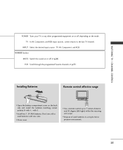
...correct polarity (+ with +, - NUMBER button MUTE Switch the sound on or off , depending on the mode. INPUT Select the desired input source: TV, AV, Component, and RGB. I Dispose of used batteries with -). Don't mix old or used batteries in a recycle bin to preserve environment. ...I Install two 1.5V AAA batteries. I Use a remote control up to the last TV channel. POWER TV INPUT MTS A.PROG MEMORY/ERASE CAPTION 1 2 3 4 56 7 8 9 0 MUTE FCR I Close cover. with new ones. TV In AV, Component, and RGB input sources, screen returns to 7 meters distance and 30...
...correct polarity (+ with +, - NUMBER button MUTE Switch the sound on or off , depending on the mode. INPUT Select the desired input source: TV, AV, Component, and RGB. I Dispose of used batteries with -). Don't mix old or used batteries in a recycle bin to preserve environment. ...I Install two 1.5V AAA batteries. I Use a remote control up to the last TV channel. POWER TV INPUT MTS A.PROG MEMORY/ERASE CAPTION 1 2 3 4 56 7 8 9 0 MUTE FCR I Close cover. with new ones. TV In AV, Component, and RGB input sources, screen returns to 7 meters distance and 30...
Owner's Manual
Page 28
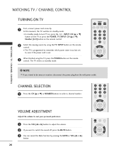
...8 9 0 MUTE FCR CH VOL ENTER VOL CH 0 MUTE FCR CH VOL ENTER VOL CH I In standby mode to turn TV on, press the , INPUT, CH (D or E) button on the TV or press the POWER, TV, INPUT, CH (D or E), Number (0~9) button on vacation, disconnect the power plug from the wall power outlet. NOTE G If... which power state it was last set to switch the sound off, press the MUTE button. 3 You can cancel the Mute function by using the TV, press the POWER button on the remote control. VOLUME ADJUSTMENT Adjust the volume to suit your personal preference. 1 Press the VOL (F or G) button to...
...8 9 0 MUTE FCR CH VOL ENTER VOL CH 0 MUTE FCR CH VOL ENTER VOL CH I In standby mode to turn TV on, press the , INPUT, CH (D or E) button on the TV or press the POWER, TV, INPUT, CH (D or E), Number (0~9) button on vacation, disconnect the power plug from the wall power outlet. NOTE G If... which power state it was last set to switch the sound off, press the MUTE button. 3 You can cancel the Mute function by using the TV, press the POWER button on the remote control. VOLUME ADJUSTMENT Adjust the volume to suit your personal preference. 1 Press the VOL (F or G) button to...


