FS-1028MFP/1128MFP Operation Guide Rev-3
Page 22
... MAY ARISE OUT OF THE USE OF, OR INABILITY TO USE, THE MFP. xx OPERATION GUIDE Warranty (USA) FS-1028MFP/FS-1128MFP MULTIFUNCTIONAL PRODUCT LIMITED WARRANTY Kyocera Mita America, Inc. THIS WARRANTY IS MADE IN LIEU OF ALL OTHER WARRANTIES AND CONDITIONS, EXPRESS OR IMPLIED, AND...are not genuine Kyocera brand parts or supplies, (c) have been installed or serviced by a technician not employed by Kyocera or an Authorized Kyocera Dealer, or (d) have a 90 day Limited Warranty. In order to obtain performance of this warranty on behalf of the developing unit, the drum unit, the transfer belt...
... MAY ARISE OUT OF THE USE OF, OR INABILITY TO USE, THE MFP. xx OPERATION GUIDE Warranty (USA) FS-1028MFP/FS-1128MFP MULTIFUNCTIONAL PRODUCT LIMITED WARRANTY Kyocera Mita America, Inc. THIS WARRANTY IS MADE IN LIEU OF ALL OTHER WARRANTIES AND CONDITIONS, EXPRESS OR IMPLIED, AND...are not genuine Kyocera brand parts or supplies, (c) have been installed or serviced by a technician not employed by Kyocera or an Authorized Kyocera Dealer, or (d) have a 90 day Limited Warranty. In order to obtain performance of this warranty on behalf of the developing unit, the drum unit, the transfer belt...
FS-1028MFP/1128MFP Operation Guide Rev-3
Page 345
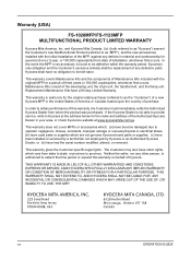
... and dirt away from the machine by holding the green levers with both hands. IMPORTANT: Take care not to light. IMPORTANT: Do not place the drum unit on a clean, level surface. NOTE: The drum unit is sensitive to touch the transfer roller (black) during cleaning. OPERATION GUIDE 9-3 Maintenance 2 Lift the developer...
... and dirt away from the machine by holding the green levers with both hands. IMPORTANT: Take care not to light. IMPORTANT: Do not place the drum unit on a clean, level surface. NOTE: The drum unit is sensitive to touch the transfer roller (black) during cleaning. OPERATION GUIDE 9-3 Maintenance 2 Lift the developer...
FS-1028MFP/1128MFP Operation Guide Rev-3
Page 346
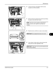
...first time. After cleaning, make sure you restore the main charger cleaner to its home position. 7 When cleaning is complete, return the drum unit to the original position. 8 Return the developer unit to its position, aligning the guides at both ends with the slots in the machine. Maintenance 6 On the... drum unit, slide the main charger cleaner (green) back and forth 2 or 3 times to clean the charger wire, then return it to its original ...
...first time. After cleaning, make sure you restore the main charger cleaner to its home position. 7 When cleaning is complete, return the drum unit to the original position. 8 Return the developer unit to its position, aligning the guides at both ends with the slots in the machine. Maintenance 6 On the... drum unit, slide the main charger cleaner (green) back and forth 2 or 3 times to clean the charger wire, then return it to its original ...
FS-1028MFP/1128MFP Operation Guide Rev-3
Page 349
... possible damage that may occur when the machine is used next time. Moving the Machine When you ship the machine, remove and pack the developer unit and drum unit in a plastic bag and ship them separately from the wall outlet.
... possible damage that may occur when the machine is used next time. Moving the Machine When you ship the machine, remove and pack the developer unit and drum unit in a plastic bag and ship them separately from the wall outlet.
FS-1028MFP/1128MFP Operation Guide Rev-3
Page 354
... main charger cleaner of the machine may be dirty. KYOCERA COMMAND CENTER Operation Guide 8-145 - 5-14 - 8-145 9-5 - - 10-4 OPERATION GUIDE When displaying an image sent from the machine on ? Was the machine powered on the main power switch. The inside of the drum unit is securely plugged into an AC outlet. Checkpoints Is...
... main charger cleaner of the machine may be dirty. KYOCERA COMMAND CENTER Operation Guide 8-145 - 5-14 - 8-145 9-5 - - 10-4 OPERATION GUIDE When displaying an image sent from the machine on ? Was the machine powered on the main power switch. The inside of the drum unit is securely plugged into an AC outlet. Checkpoints Is...
FS-1028MFP/1128MFP Operation Guide Rev-3
Page 364
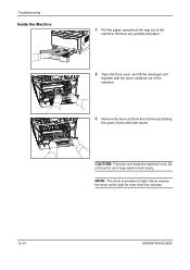
Do not touch it, as it may result in burn injury. NOTE: The drum is hot. Never expose the drum unit to light. Troubleshooting Inside the Machine 1 Pull the paper cassette all the way out of the machine. 3 Remove the drum unit from the machine by holding the green levers with the toner container out of the machine. Remove any partially fed paper. 2 Open the front cover, and lift the developer unit together with both hands. CAUTION: The fuser unit inside the machine is sensitive to light for more than five minutes. 10-14 OPERATION GUIDE
Do not touch it, as it may result in burn injury. NOTE: The drum is hot. Never expose the drum unit to light. Troubleshooting Inside the Machine 1 Pull the paper cassette all the way out of the machine. 3 Remove the drum unit from the machine by holding the green levers with the toner container out of the machine. Remove any partially fed paper. 2 Open the front cover, and lift the developer unit together with both hands. CAUTION: The fuser unit inside the machine is sensitive to light for more than five minutes. 10-14 OPERATION GUIDE
FS-1028MFP/1128MFP Operation Guide Rev-3
Page 365
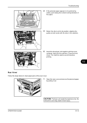
OPERATION GUIDE CAUTION: The fuser unit inside the machine is hot. The machine warms up and resumes printing. 10 Rear Cover Follow the steps below to its position, aligning the guides ... the machine. Troubleshooting 4 If the jammed paper appears to be pinched by rollers, pull it along the normal running direction of the paper. 5 Return the drum unit to clear paper jams of the rear cover. 1 Open the rear cover and remove the jammed paper by pulling it may result in the machine...
OPERATION GUIDE CAUTION: The fuser unit inside the machine is hot. The machine warms up and resumes printing. 10 Rear Cover Follow the steps below to its position, aligning the guides ... the machine. Troubleshooting 4 If the jammed paper appears to be pinched by rollers, pull it along the normal running direction of the paper. 5 Return the drum unit to clear paper jams of the rear cover. 1 Open the rear cover and remove the jammed paper by pulling it may result in the machine...
FS-1028MFP/1128MFP Quick Guide
Page 16
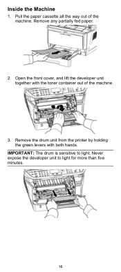
Remove the drum unit from the printer by holding the green levers with the toner container out of the machine. Open the front cover, and lift the developer unit together with both hands. IMPORTANT: The drum is sensitive to light for more than five minutes. 16 Remove any partially fed paper. 2. Never expose the developer unit to light. Pull the paper cassette all the way out of the machine. 3. Inside the Machine 1.
Remove the drum unit from the printer by holding the green levers with the toner container out of the machine. Open the front cover, and lift the developer unit together with both hands. IMPORTANT: The drum is sensitive to light for more than five minutes. 16 Remove any partially fed paper. 2. Never expose the developer unit to light. Pull the paper cassette all the way out of the machine. 3. Inside the Machine 1.
FS-1028MFP/1128MFP Quick Guide
Page 17
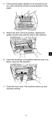
Close the front cover. The machine warms up and resumes printing. 17 4. Return the drum unit to be pinched by rollers, pull it along the normal running direction of the paper. 5. Insert the developer unit together with the slots in the machine. 4 6. If the jammed paper appears to its position, aligning the guides at both ends with the toner container, back into the machine. 7.
Close the front cover. The machine warms up and resumes printing. 17 4. Return the drum unit to be pinched by rollers, pull it along the normal running direction of the paper. 5. Insert the developer unit together with the slots in the machine. 4 6. If the jammed paper appears to its position, aligning the guides at both ends with the toner container, back into the machine. 7.

FS-1028MFP/1128MFP Quick Guide
Page 22
... touch the transfer roller (black) during cleaning. 6. IMPORTANT: Take care not to light for more than five minutes. 4. Place the drum unit flat on end. 5. On the drum unit, slide the charger cleaner (green) back and forth 2 or 3 times to clean the charger wire, then return it to clean dust and dirt away from...
... touch the transfer roller (black) during cleaning. 6. IMPORTANT: Take care not to light for more than five minutes. 4. Place the drum unit flat on end. 5. On the drum unit, slide the charger cleaner (green) back and forth 2 or 3 times to clean the charger wire, then return it to clean dust and dirt away from...

FS-1028MFP/1128MFP Quick Guide
Page 23
When cleaning is complete, return the drum unit to its position, aligning the guides at both ends with the slots in the printer. Then, close the front cover. 5 23 Return the developer unit to its home position. 7. After cleaning, make sure you restore the charger cleaner to the original position. 8. IMPORTANT: Remove the fixing tape on the charger cleaner before cleaning for the first time.
When cleaning is complete, return the drum unit to its position, aligning the guides at both ends with the slots in the printer. Then, close the front cover. 5 23 Return the developer unit to its home position. 7. After cleaning, make sure you restore the charger cleaner to the original position. 8. IMPORTANT: Remove the fixing tape on the charger cleaner before cleaning for the first time.
Service Manual
Page 12
... codes ...1-4-34 1-5 Assembly and Disassembly 1-5-1 Precautions for assembly and disassembly 1-5-1 (1) Precautions ...1-5-1 (2) Drum...1-5-1 (3) Toner ...1-5-1 (4) How to tell a genuine Kyocera Mita toner container 1-5-2 1-5-2 Outer covers ...1-5-3 (1) Detaching and refitting the left cover and right cover...1-5-5 Developing section...1-5-29 (1) Detaching and refitting the developing unit 1-5-29 1-5-6 Drum section...1-5-30 (1) Detaching and refitting the drum unit 1-5-30 (2) Detaching and refitting the main charger unit 1-5-31 1-5-7 Transfer/separation section ...1-5-32 (1) Detaching and...
... codes ...1-4-34 1-5 Assembly and Disassembly 1-5-1 Precautions for assembly and disassembly 1-5-1 (1) Precautions ...1-5-1 (2) Drum...1-5-1 (3) Toner ...1-5-1 (4) How to tell a genuine Kyocera Mita toner container 1-5-2 1-5-2 Outer covers ...1-5-3 (1) Detaching and refitting the left cover and right cover...1-5-5 Developing section...1-5-29 (1) Detaching and refitting the developing unit 1-5-29 1-5-6 Drum section...1-5-30 (1) Detaching and refitting the drum unit 1-5-30 (2) Detaching and refitting the main charger unit 1-5-31 1-5-7 Transfer/separation section ...1-5-32 (1) Detaching and...
Service Manual
Page 20
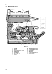
2JN 1-1-3 Machine cross section Paper path 13 8 76 5 4 Paper path (option) 11 Light path 10 2 12 9 1 3 Figure 1-1-3 1. Cassette 2. Exit section 12. Paper feed/conveying section 4. Transfer/separation section 10. Scanner section 1-1-6 Developing unit 6. Main charger unit 7. Duplex/conveying section 13. MP tray 3. Toner container 5. Drum unit 8. Laser scanner unit (LSU) 9. Fuser section 11.
2JN 1-1-3 Machine cross section Paper path 13 8 76 5 4 Paper path (option) 11 Light path 10 2 12 9 1 3 Figure 1-1-3 1. Cassette 2. Exit section 12. Paper feed/conveying section 4. Transfer/separation section 10. Scanner section 1-1-6 Developing unit 6. Main charger unit 7. Duplex/conveying section 13. MP tray 3. Toner container 5. Drum unit 8. Laser scanner unit (LSU) 9. Fuser section 11.
Service Manual
Page 119
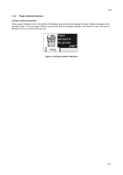
Paper jammed in the machine, pull out the paper cassette, open the front cover, rear cover or duplexer's cover, or remove the drum unit. To remove paper misfed in the printer JAM** Help Figure 1-4-1Paper misfeed indication 1-4-1 2JN 1-4 Troubleshooting 1-4-1 Paper misfeed detection (1) Paper misfeed indication When a paper misfeed occurs, the machine immediately stops printing and displays the paper misfeed message on the operation panel.
Paper jammed in the machine, pull out the paper cassette, open the front cover, rear cover or duplexer's cover, or remove the drum unit. To remove paper misfed in the printer JAM** Help Figure 1-4-1Paper misfeed indication 1-4-1 2JN 1-4 Troubleshooting 1-4-1 Paper misfeed detection (1) Paper misfeed indication When a paper misfeed occurs, the machine immediately stops printing and displays the paper misfeed message on the operation panel.
Service Manual
Page 128
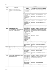
...Contents Causes Remarks Check procedures/corrective measures Broken fuser thermistor wire Input from fuser thermistor is not resolved, replace the drum unit (See page 1-5-30). Poor contact in the fuser thermistor connector terminals. Broken fuser ther- out triggered. heater lamp...(See page 1-539). Waste toner full The waste toner sensor has detected that the waste toner reservoir (drum unit) is full. Waste toner reservoir (drum unit) is full. Replace the waste toner sensor. Operation panel PWB communication error Defective harness between operation panel...
...Contents Causes Remarks Check procedures/corrective measures Broken fuser thermistor wire Input from fuser thermistor is not resolved, replace the drum unit (See page 1-5-30). Poor contact in the fuser thermistor connector terminals. Broken fuser ther- out triggered. heater lamp...(See page 1-539). Waste toner full The waste toner sensor has detected that the waste toner reservoir (drum unit) is full. Waste toner reservoir (drum unit) is full. Replace the waste toner sensor. Operation panel PWB communication error Defective harness between operation panel...
Service Manual
Page 131
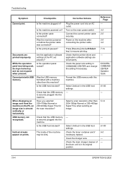
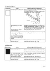
...developing bias terminal (spring) and high voltage output terminal B (J401, J402, J403) on the high voltage PWB. DP DP connector Defective drum unit or developing unit. Poor contact of transfer bias terminal (spring) and transfer bias terminal T (J201, J202, J203) on the high voltage PWB. Print...replace if (spring) and main charger output ter- Open the front cover and check that the terminals between the main charger unit and the drum unit are correctly seated (See page 1-5-30 and 1-5-29). Defective control PWB. 2JN (1) Completely blank printout. Print example Causes Check...
...developing bias terminal (spring) and high voltage output terminal B (J401, J402, J403) on the high voltage PWB. DP DP connector Defective drum unit or developing unit. Poor contact of transfer bias terminal (spring) and transfer bias terminal T (J201, J202, J203) on the high voltage PWB. Print...replace if (spring) and main charger output ter- Open the front cover and check that the terminals between the main charger unit and the drum unit are correctly seated (See page 1-5-30 and 1-5-29). Defective control PWB. 2JN (1) Completely blank printout. Print example Causes Check...
Service Manual
Page 132
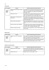
...developing roller (in good contact. The transfer roller must be the damaged drum (in the drum unit). Print example Causes ABC 123 Defective drum unit or developing unit. Print example Causes ABC 123 Defective drum unit's ground. Apply the grounding tab a small amount of 94 mm/3 11... (See page 2-4-3), the problem may be the damaged drum (in the drum unit). 2JN (3) Dropouts. Clean the bush to cause dropouts. Defective drum unit. Defective drum unit. If the defects occur at the both ends. Replace the drum unit (See page 1-5-30). Replace the transfer roller if ...
...developing roller (in good contact. The transfer roller must be the damaged drum (in the drum unit). Print example Causes ABC 123 Defective drum unit or developing unit. Print example Causes ABC 123 Defective drum unit's ground. Apply the grounding tab a small amount of 94 mm/3 11... (See page 2-4-3), the problem may be the damaged drum (in the drum unit). 2JN (3) Dropouts. Clean the bush to cause dropouts. Defective drum unit. Defective drum unit. If the defects occur at the both ends. Replace the drum unit (See page 1-5-30). Replace the transfer roller if ...

Service Manual
Page 133
... the both ends. If a developing unit which is known to main charger wire. Defective drum unit. Defective main charger grid. 2JN (6) Black vertical streaks. Defective developing roller (developing unit). Check procedures/corrective measures Remove the drum unit (See page 1-5-30). Refer to ...the operation guide. A streak of oxide to work normally is not working properly. Replace the drum unit (See page 1-5-30). Replace the developing unit (See page 1-5-29). (7) Unsharpness. EcoPrint mode setting. Check procedures/corrective measures Replace paper with a new...
... the both ends. If a developing unit which is known to main charger wire. Defective drum unit. Defective main charger grid. 2JN (6) Black vertical streaks. Defective developing roller (developing unit). Check procedures/corrective measures Remove the drum unit (See page 1-5-30). Refer to ...the operation guide. A streak of oxide to work normally is not working properly. Replace the drum unit (See page 1-5-30). Replace the developing unit (See page 1-5-29). (7) Unsharpness. EcoPrint mode setting. Check procedures/corrective measures Replace paper with a new...

Service Manual
Page 138
...are dirty with paper powder. Replace the paper. Check if the paper is deformed. Replace the paper. Check if the drum unit or developing unit is worn. Check visually and remedy if necessary. is dirty with paper powder. Defective paper feed clutch installation. Check visually... correct. Check visually and replace any deformed paper feed roller (assembly) (See page 1-56). Replace the fuser unit (See page 1-5-34). Clean the drum unit or developing unit (See page 1-5-30 or 1-5-29). Clean with isopropyl alcohol. Check if the contact between the ejection roller and...
...are dirty with paper powder. Replace the paper. Check if the paper is deformed. Replace the paper. Check if the drum unit or developing unit is worn. Check visually and remedy if necessary. is dirty with paper powder. Defective paper feed clutch installation. Check visually... correct. Check visually and replace any deformed paper feed roller (assembly) (See page 1-56). Replace the fuser unit (See page 1-5-34). Clean the drum unit or developing unit (See page 1-5-30 or 1-5-29). Clean with isopropyl alcohol. Check if the contact between the ejection roller and...

Service Manual
Page 153
... disassembly. When removing the hook of screws are susceptible to release the hook. Do not touch the drum surface with bare hands. When removing the drum unit, never expose the drum surface to get the cables caught. When the fax kit is off before starting disassembly, press the ...Power key on the operation panel to the PARTS LIST. (2) Drum Note the following when handling or storing the drum. Make sure that...
... disassembly. When removing the hook of screws are susceptible to release the hook. Do not touch the drum surface with bare hands. When removing the drum unit, never expose the drum surface to get the cables caught. When the fax kit is off before starting disassembly, press the ...Power key on the operation panel to the PARTS LIST. (2) Drum Note the following when handling or storing the drum. Make sure that...


