Service Manual
Page 4
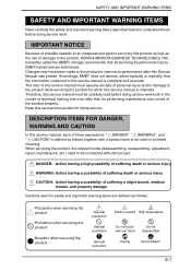
... meaning. IMPORTANT NOTICE Because of possible hazards to an inexperienced person servicing this Service Manual was printed. Keep this service manual must assume all servicing be used for safety and important warning items are defined as follows together with utmost care. When servicing the product, the relevant works (disassembling, reassembling, adjustment, repair, maintenance, etc.) need to be conducted with a symbol mark to be performed only...
... meaning. IMPORTANT NOTICE Because of possible hazards to an inexperienced person servicing this Service Manual was printed. Keep this service manual must assume all servicing be used for safety and important warning items are defined as follows together with utmost care. When servicing the product, the relevant works (disassembling, reassembling, adjustment, repair, maintenance, etc.) need to be conducted with a symbol mark to be performed only...
Service Manual
Page 5
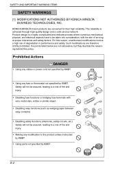
...Actions DANGER • Using any cables or power cord not specified by KMBT. • Using any modification to the product unless instructed by KMBT • Using parts not specified by KMBT. For this policy. the points listed below are not ...paper between relay contacts) • Disabling safety functions (interlocks, safety circuits, etc.) Safety will not be taken into consideration, with the aim of fire and injury. • Making any fuse or thermostat not specified by KMBT S-2 SAFETY AND IMPORTANT WARNING ITEMS SAFETY WARNINGS [1] MODIFICATIONS NOT AUTHORIZED BY KONICA MINOLTA...
...Actions DANGER • Using any cables or power cord not specified by KMBT. • Using any modification to the product unless instructed by KMBT • Using parts not specified by KMBT. For this policy. the points listed below are not ...paper between relay contacts) • Disabling safety functions (interlocks, safety circuits, etc.) Safety will not be taken into consideration, with the aim of fire and injury. • Making any fuse or thermostat not specified by KMBT S-2 SAFETY AND IMPORTANT WARNING ITEMS SAFETY WARNINGS [1] MODIFICATIONS NOT AUTHORIZED BY KONICA MINOLTA...
Service Manual
Page 7
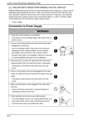
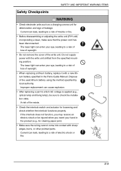
... SERVICE KONICA MINOLTA brand products are extensively tested before shipping, to ensure that mains voltage is as the plug. In order to maintain safety and reliability, the CE must not exceed the rating of fire. • Check whether the product is grounded properly. If current leakage occurs in an ungrounded product, you may result. • Make...
... SERVICE KONICA MINOLTA brand products are extensively tested before shipping, to ensure that mains voltage is as the plug. In order to maintain safety and reliability, the CE must not exceed the rating of fire. • Check whether the product is grounded properly. If current leakage occurs in an ungrounded product, you may result. • Make...
Service Manual
Page 12
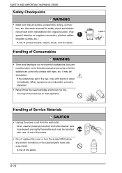
... corona unit for clearing paper jam). • Make sure the wiring cannot come into contact with sharp edges, burrs, or other pointed parts. Current can leak, leading to check the installation state. Improper replacement can enter your hand in the Parts Guide Manual. A risk of the used lithium battery using the method specified by local authority. The laser light can cause explosion. • After replacing a part to which...
... corona unit for clearing paper jam). • Make sure the wiring cannot come into contact with sharp edges, burrs, or other pointed parts. Current can leak, leading to check the installation state. Improper replacement can enter your hand in the Parts Guide Manual. A risk of the used lithium battery using the method specified by local authority. The laser light can cause explosion. • After replacing a part to which...
Service Manual
Page 13
... not replace the cover or turn the product ON before any solvent remnants on the cleaned parts have been reinstalled in the eye, rinse with care. A risk of Service Materials CAUTION • Unplug the power cord from the wall outlet. SAFETY AND IMPORTANT WARNING ITEMS Safety Checkpoints WARNING • Make sure that were removed for safety check and maintenance have fully...
... not replace the cover or turn the product ON before any solvent remnants on the cleaned parts have been reinstalled in the eye, rinse with care. A risk of Service Materials CAUTION • Unplug the power cord from the wall outlet. SAFETY AND IMPORTANT WARNING ITEMS Safety Checkpoints WARNING • Make sure that were removed for safety check and maintenance have fully...
Service Manual
Page 26
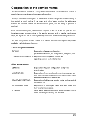
..., product specifications, unit configuration, and paper path COMPOSITION/OPERATION: Explanation of configuration of each unit, operating system, and control system GENERAL: MAINTENANCE: ADJUSTMENT/SETTING: TROUBLESHOOTING: APPENDIX: Explanation of system configuration, and product specifications Explanation of service schedule, maintenance steps, service tools, removal/reinstallation methods of jam codes and error codes, and their countermeasures etc. Explanation of lists of major parts, and firmware version up method etc. Composition of the service manual This service manual consists...
..., product specifications, unit configuration, and paper path COMPOSITION/OPERATION: Explanation of configuration of each unit, operating system, and control system GENERAL: MAINTENANCE: ADJUSTMENT/SETTING: TROUBLESHOOTING: APPENDIX: Explanation of system configuration, and product specifications Explanation of service schedule, maintenance steps, service tools, removal/reinstallation methods of jam codes and error codes, and their countermeasures etc. Explanation of lists of major parts, and firmware version up method etc. Composition of the service manual This service manual consists...
Service Manual
Page 32
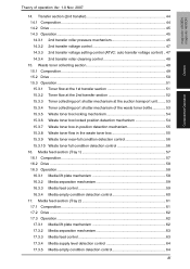
....3.8 Waste toner flow in the waste toner box 55 15.3.9 Waste toner near-full condition detection control 56 15.3.10 Waste toner full condition detection control 56 16. Transfer section (2nd transfer 44 14.1 Composition...44 14.2 Drive ...45 14.3 Operation ...45 14.3.1 2nd transfer roller pressure mechanism 45 14.3.2 2nd transfer voltage control 47 14.3.3 2nd transfer voltage setting control (ATVC: auto transfer voltage control) .. 47 14.3.4 2nd transfer roller cleaning control 48...
....3.8 Waste toner flow in the waste toner box 55 15.3.9 Waste toner near-full condition detection control 56 15.3.10 Waste toner full condition detection control 56 16. Transfer section (2nd transfer 44 14.1 Composition...44 14.2 Drive ...45 14.3 Operation ...45 14.3.1 2nd transfer roller pressure mechanism 45 14.3.2 2nd transfer voltage control 47 14.3.3 2nd transfer voltage setting control (ATVC: auto transfer voltage control) .. 47 14.3.4 2nd transfer roller cleaning control 48...
Service Manual
Page 37
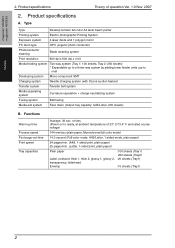
... Transfer belt system Media separating system Curvature separation + charge-neutralizing system Fusing system Belt fusing Media exit system Face down (Output tray capacity: A4S/Letter, 200 sheets) B. Product specifications A. Type Type Desktop tandem full-color A4 laser beam printer Printing system Electro photographic Printing System Exposure system 4 laser diode and 1 polygon mirror PC drum type OPC (organic photo conductor) Photoconductor cleaning Blade cleaning system Print resolution 600 dpi x 600 dpi x 4 bit Media feeding...
... Transfer belt system Media separating system Curvature separation + charge-neutralizing system Fusing system Belt fusing Media exit system Face down (Output tray capacity: A4S/Letter, 200 sheets) B. Product specifications A. Type Type Desktop tandem full-color A4 laser beam printer Printing system Electro photographic Printing System Exposure system 4 laser diode and 1 polygon mirror PC drum type OPC (organic photo conductor) Photoconductor cleaning Blade cleaning system Print resolution 600 dpi x 600 dpi x 4 bit Media feeding...
Service Manual
Page 39
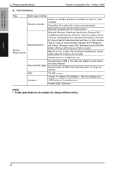
... recommend installing the newest patch), Mac OS X Server (10.2 or later) Red Hat Linux 9.0, SuSE Linux 8.2 Free hard disk space Approximately 20 MB of free hard disk space for printer driver and Status Monitor Approximately 128 MB of operation Ver. 1.0 Nov. 2007 G. Product specifications Theory of free hard disk space for image processing RAM 128 MB or more 10Base-T/100Base-TX/1000Base-T Ethernet interface port Interfaces USB...
... recommend installing the newest patch), Mac OS X Server (10.2 or later) Red Hat Linux 9.0, SuSE Linux 8.2 Free hard disk space Approximately 20 MB of free hard disk space for printer driver and Status Monitor Approximately 128 MB of operation Ver. 1.0 Nov. 2007 G. Product specifications Theory of free hard disk space for image processing RAM 128 MB or more 10Base-T/100Base-TX/1000Base-T Ethernet interface port Interfaces USB...
Service Manual
Page 49
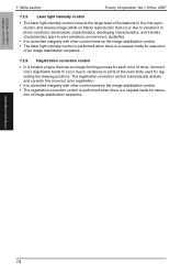
... tion of the main body used for execu- Write section Theory of operation Ver.1.0 Nov. 2007 7.2.5 Laser light intensity control • The laser light intensity control corrects the target level of fluctuations in fine line reproduction and reverse image (white on black) reproduction that occur due to variations in photo conductor electrostatic characteristics, developing characteristics, and transfer characteristics (part-to-part variations, environment, durability). • It...
... tion of the main body used for execu- Write section Theory of operation Ver.1.0 Nov. 2007 7.2.5 Laser light intensity control • The laser light intensity control corrects the target level of fluctuations in fine line reproduction and reverse image (white on black) reproduction that occur due to variations in photo conductor electrostatic characteristics, developing characteristics, and transfer characteristics (part-to-part variations, environment, durability). • It...
Service Manual
Page 53
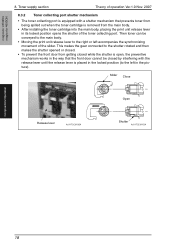
... when the toner cartridge is removed from the main body. • After installing the toner cartridge into the main body, placing the print unit release lever in its locked position opens the shutter of the toner collecting port. magicolor 4650EN magicolor 4650DN 8. Slider Close Open Release lever A011T2C010DA Shutter A011T2C011DA Composition/Operation 18 Toner supply section Theory of the slider. This makes the gear connected to...
... when the toner cartridge is removed from the main body. • After installing the toner cartridge into the main body, placing the print unit release lever in its locked position opens the shutter of the toner collecting port. magicolor 4650EN magicolor 4650DN 8. Slider Close Open Release lever A011T2C010DA Shutter A011T2C011DA Composition/Operation 18 Toner supply section Theory of the slider. This makes the gear connected to...
Service Manual
Page 60
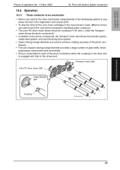
... uneven pitch. • To stop the drive for the color toner cartridges in the monochrome mode, different motors are used to drive the color photo conductors and black photo conductor. • The color PC drum motor drives the photo conductor/Y, M, and C, while the Transport motor drives the photo conductor/K. • In addition to the photo conductor/K, the Transport motor also drives the transfer system, media feed system, and synchronizing drive system. • Gears having...
... uneven pitch. • To stop the drive for the color toner cartridges in the monochrome mode, different motors are used to drive the color photo conductors and black photo conductor. • The color PC drum motor drives the photo conductor/Y, M, and C, while the Transport motor drives the photo conductor/K. • In addition to the photo conductor/K, the Transport motor also drives the transfer system, media feed system, and synchronizing drive system. • Gears having...
Service Manual
Page 72
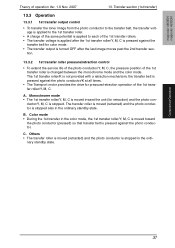
... stopped also in the ordi- Composition/Operation 37 Transfer section (1st transfer) 13.3 Operation 13.3.1 1st transfer output control • To transfer the toner image from the photo conductor to the transfer belt, the transfer voltage is applied to each of the 1st transfer roller/Y, M, C. Monochrome mode • The 1st transfer roller/Y, M, C is moved inward the unit (for color mode. • The transfer output is turned OFF after the 1st transfer roller/Y, M, C is applied to the 1st transfer roller...
... stopped also in the ordi- Composition/Operation 37 Transfer section (1st transfer) 13.3 Operation 13.3.1 1st transfer output control • To transfer the toner image from the photo conductor to the transfer belt, the transfer voltage is applied to each of the 1st transfer roller/Y, M, C. Monochrome mode • The 1st transfer roller/Y, M, C is moved inward the unit (for color mode. • The transfer output is turned OFF after the 1st transfer roller/Y, M, C is applied to the 1st transfer roller...
Service Manual
Page 77
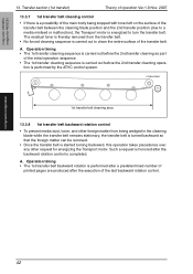
... removed. • Once the transfer belt is started turning backward, this operation takes precedence over any other foreign matter from the transfer belt. • No forced cleaning sequence is completed. Operation timing • The 1st transfer belt backward rotation is performed after a predetermined number of the initial operation sequence. • The 1st transfer cleaning sequence is carried out before the 2nd transfer cleaning as part of printed pages...
... removed. • Once the transfer belt is started turning backward, this operation takes precedence over any other foreign matter from the transfer belt. • No forced cleaning sequence is completed. Operation timing • The 1st transfer belt backward rotation is performed after a predetermined number of the initial operation sequence. • The 1st transfer cleaning sequence is carried out before the 2nd transfer cleaning as part of printed pages...
Service Manual
Page 83
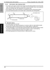
... 2nd transfer roller. Operation timing • The power switch is turned ON. • The 2nd transfer roller cleaning sequence is carried out after the intermediate transfer belt has been cleaned during the cleaning procedure. • The toner transferred back to a stop , a new cleaning sequence is carried out before the printer is brought to the transfer belt is carried out when a media size error occurs. Transfer section (2nd transfer) Theory of the 2nd transfer roller to be transferred back...
... 2nd transfer roller. Operation timing • The power switch is turned ON. • The 2nd transfer roller cleaning sequence is carried out after the intermediate transfer belt has been cleaned during the cleaning procedure. • The toner transferred back to a stop , a new cleaning sequence is carried out before the printer is brought to the transfer belt is carried out when a media size error occurs. Transfer section (2nd transfer) Theory of the 2nd transfer roller to be transferred back...
Service Manual
Page 111
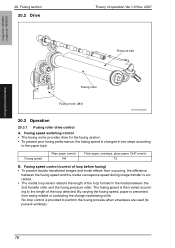
... changed in the media between the fusing speed and the media conveyance speed during image transfer is provided to perform the fusing process when envelopes are used (to the length of operation Ver.1.0 Nov. 2007 Pressure belt Composition/Operation Fusing roller Fusing motor (M4) A011T2C543AA 20.3 Operation 20.3.1 Fusing roller drive control A. Fusing speed Plain paper (mm/s) 144 Thick paper, envelops, gloss paper, OHP (mm/s) 72 B. Fusing speed switching control...
... changed in the media between the fusing speed and the media conveyance speed during image transfer is provided to perform the fusing process when envelopes are used (to the length of operation Ver.1.0 Nov. 2007 Pressure belt Composition/Operation Fusing roller Fusing motor (M4) A011T2C543AA 20.3 Operation 20.3.1 Fusing roller drive control A. Fusing speed Plain paper (mm/s) 144 Thick paper, envelops, gloss paper, OHP (mm/s) 72 B. Fusing speed switching control...
Service Manual
Page 115
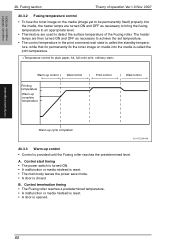
... fixed) properly into the media is opened. 80 Control start timing • The power switch is turned ON. • A malfunction or media misfeed is reset. • The main body leaves the power save mode. • A door is provided until the Fusing roller reaches the predetermined level. Warm-up control Wait control Printing temperature Warm-up complete temperature Print control Wait control Warm-up cycle completed A011T2C544AA 20.3.3 Warm-up control • Control...
... fixed) properly into the media is opened. 80 Control start timing • The power switch is turned ON. • A malfunction or media misfeed is reset. • The main body leaves the power save mode. • A door is provided until the Fusing roller reaches the predetermined level. Warm-up control Wait control Printing temperature Warm-up complete temperature Print control Wait control Warm-up cycle completed A011T2C544AA 20.3.3 Warm-up control • Control...
Service Manual
Page 118
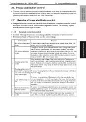
.... Image stabilization control 21. Control name Purpose IDC sensor offset value To check the low gain output value and offset voltage value of each toner cartridge, a leak image (background leak, image area leak) results. Developing bias control 3 (control of the maximum To correct the target amount of toner sticking to the transfer belt to the clear transfer belt surface. magicolor 4650EN magicolor 4650DN Composition/Operation Theory of toner...
.... Image stabilization control 21. Control name Purpose IDC sensor offset value To check the low gain output value and offset voltage value of each toner cartridge, a leak image (background leak, image area leak) results. Developing bias control 3 (control of the maximum To correct the target amount of toner sticking to the transfer belt to the clear transfer belt surface. magicolor 4650EN magicolor 4650DN Composition/Operation Theory of toner...
Service Manual
Page 119
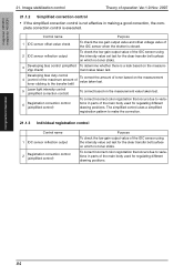
Composition/Operation 84 To correct incorrect color registration that occurs due to make the correction. 21.1.3 Individual registration control Control name 1 IDC sensor reflection output 2 Registration correction control (simplified control) Purpose To check the low gain output value of the main body used for the clear transfer belt surface on which no toner sticks. Control name Purpose 1 IDC sensor offset value check To check the low gain output value and offset...
Composition/Operation 84 To correct incorrect color registration that occurs due to make the correction. 21.1.3 Individual registration control Control name 1 IDC sensor reflection output 2 Registration correction control (simplified control) Purpose To check the low gain output value of the main body used for the clear transfer belt surface on which no toner sticks. Control name Purpose 1 IDC sensor offset value check To check the low gain output value and offset...
Service Manual
Page 145
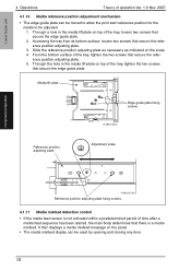
... the panel. • The media misfeed display can be moved to allow the print start reference position for the media to be reset by opening and closing any door. 10 Operations Theory of time after a media feed sequence has been started, the main body determines that there is a media misfeed. Media lift plate Edge guide plate fixing screws 4138to2125c0 Reference position adjusting plate Adjustment scale Composition/Operation 4138to2123c0...
... the panel. • The media misfeed display can be moved to allow the print start reference position for the media to be reset by opening and closing any door. 10 Operations Theory of time after a media feed sequence has been started, the main body determines that there is a media misfeed. Media lift plate Edge guide plate fixing screws 4138to2125c0 Reference position adjusting plate Adjustment scale Composition/Operation 4138to2123c0...


