Dimension Guide
Page 1
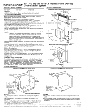
... only 15-amp fused, electrical circuit is 13" (33 cm). It is located on the model/serial rating plate. q Grounded electrical outlet is installed directly behind the cooktop. See the Countertop Cutout Dimensions section. The cutout locations for this range hood must conform to change without notice. W10342489D 1/31/2012 LOCATION REQUIREMENTS NOTE: Downdraft vent is required. q Cabinet opening dimensions that applies to change materials and specifications without notice. For Mobile Home Installations The installation of the cooktop. Instructions packed...
... only 15-amp fused, electrical circuit is 13" (33 cm). It is located on the model/serial rating plate. q Grounded electrical outlet is installed directly behind the cooktop. See the Countertop Cutout Dimensions section. The cutout locations for this range hood must conform to change without notice. W10342489D 1/31/2012 LOCATION REQUIREMENTS NOTE: Downdraft vent is required. q Cabinet opening dimensions that applies to change materials and specifications without notice. For Mobile Home Installations The installation of the cooktop. Instructions packed...
Dimension Guide
Page 2
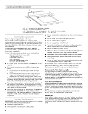
...) mounted blower motor Rear mounted blower motor C A A A A. Most island applications would still require the venting to improve Dimensions are not recommended for your application. q Do not use plastic or metal foil vent. Right vent Because Whirlpool Corporation policy includes a continuous commitment to be directed down through either interior-mounted or exterior-mounted blower installations, the vent system length should be mounted for right, left, or rear venting if needed for specific requirements in the Installation Instructions for complete cutout dimensions...
...) mounted blower motor Rear mounted blower motor C A A A A. Most island applications would still require the venting to improve Dimensions are not recommended for your application. q Do not use plastic or metal foil vent. Right vent Because Whirlpool Corporation policy includes a continuous commitment to be directed down through either interior-mounted or exterior-mounted blower installations, the vent system length should be mounted for right, left, or rear venting if needed for specific requirements in the Installation Instructions for complete cutout dimensions...
Use & Care Guide
Page 4
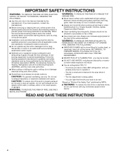
... servicing or cleaning the unit, switch power off the burner. CAUTION: For general ventilating use to an authorized service facility for examination and/or repair. ■ Sufficient air is being switched on "Kitchen Fire Safety Tips" published by qualified person(s) in accordance with all applicable codes and standards, including fire-rated construction. ■ Do not operate any fan with any solid-state speed control device. do not damage electrical wiring...
... servicing or cleaning the unit, switch power off the burner. CAUTION: For general ventilating use to an authorized service facility for examination and/or repair. ■ Sufficient air is being switched on "Kitchen Fire Safety Tips" published by qualified person(s) in accordance with all applicable codes and standards, including fire-rated construction. ■ Do not operate any fan with any solid-state speed control device. do not damage electrical wiring...
Use & Care Guide
Page 5
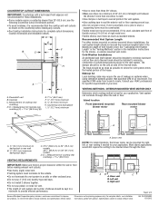
...; Vent system ■ Home power supply cable ■ 3 - Some installations require a countertop deeper than 25" (63.5 cm). INSTALLATION REQUIREMENTS Tools and Parts Gather the required tools and parts before making any tools listed here. mounted blower motor models only) ■ 10" (25.4 cm) diameter vent collar (exterior-mounted blower model only) Parts Needed ■ UL listed or CSA approved ½" (12.7 mm) conduit connector ■ Wall or roof cap with installation clearances specified on the front of this downdraft vent must be used...
...; Vent system ■ Home power supply cable ■ 3 - Some installations require a countertop deeper than 25" (63.5 cm). INSTALLATION REQUIREMENTS Tools and Parts Gather the required tools and parts before making any tools listed here. mounted blower motor models only) ■ 10" (25.4 cm) diameter vent collar (exterior-mounted blower model only) Parts Needed ■ UL listed or CSA approved ½" (12.7 mm) conduit connector ■ Wall or roof cap with installation clearances specified on the front of this downdraft vent must be used...

Use & Care Guide
Page 7
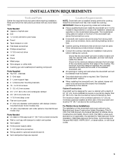
... for cooktop cutout depth and width. ■ Exterior-mounted blower systems connect with 3¹⁄₄" x 10" (8.3 x 25.4 cm) rectangular or 6" (15.2 cm) round vent system. Centerline of cooktop cutout NOTES: ■ See cooktop manufacturer's instructions for cooktop cutout depth and width. ■ Use dimensions for this vent system will depend upon your specific installation. The cutout locations for vent system cutout location that the cooktop and vent cutouts be drawn on your specific installation. Measurement of cooktop rear...
... for cooktop cutout depth and width. ■ Exterior-mounted blower systems connect with 3¹⁄₄" x 10" (8.3 x 25.4 cm) rectangular or 6" (15.2 cm) round vent system. Centerline of cooktop cutout NOTES: ■ See cooktop manufacturer's instructions for cooktop cutout depth and width. ■ Use dimensions for this vent system will depend upon your specific installation. The cutout locations for vent system cutout location that the cooktop and vent cutouts be drawn on your specific installation. Measurement of cooktop rear...
Use & Care Guide
Page 8
...., AC only, 15-amp, fused electrical circuit is proper clearance within the wall or floor before making exhaust vent cutouts. ■ Use heavy (rigid) metal vent. ■ Venting system must terminate to the outside temperatures as standard elbows. A copy of the above the wiring box cover. ■ Wire sizes must conform to the requirements of the National Electrical Code, ANSI/NFPA 70 (latest edition), or CSA Standards C22. 1-94, Canadian Electrical Code, Part 1 and C22.2 No...
...., AC only, 15-amp, fused electrical circuit is proper clearance within the wall or floor before making exhaust vent cutouts. ■ Use heavy (rigid) metal vent. ■ Venting system must terminate to the outside temperatures as standard elbows. A copy of the above the wiring box cover. ■ Wire sizes must conform to the requirements of the National Electrical Code, ANSI/NFPA 70 (latest edition), or CSA Standards C22. 1-94, Canadian Electrical Code, Part 1 and C22.2 No...

Use & Care Guide
Page 12
..., a wall or roof cap with a damper at the exit end of the vent system is required. ■ Downdraft vent is shipped with blower in down venting position so no modification is required. ■ If rear mounting of the blower motor is not required, go to the "Complete Installation (Interior-Mounted Motor)" section. ■ To mount the blower motor to the rear side of the ¹⁄₄" (6.4 mm) deep cover. Blower Motor" section. Set the cover aside. 4. NOTE: Reinstall the electrical wiring connection...
..., a wall or roof cap with a damper at the exit end of the vent system is required. ■ Downdraft vent is shipped with blower in down venting position so no modification is required. ■ If rear mounting of the blower motor is not required, go to the "Complete Installation (Interior-Mounted Motor)" section. ■ To mount the blower motor to the rear side of the ¹⁄₄" (6.4 mm) deep cover. Blower Motor" section. Set the cover aside. 4. NOTE: Reinstall the electrical wiring connection...

Use & Care Guide
Page 15
... rear of cooktop overlaps edge of the downdraft vent for matching your cooktop color are pressed in terminal box. Filters 2. Replace the terminal box cover and secure with a wall or roof cap. Connect ground wire to seal all parts and panels before servicing. Connect the 2 white wires together using UL listed wire connectors. 6. Use clamps or duct tape to green and yellow ground wire in as far as they will start. B A A. UL listed wire connectors D. Black wires E. Disconnect power. 2. Check that the circuit...
... rear of cooktop overlaps edge of the downdraft vent for matching your cooktop color are pressed in terminal box. Filters 2. Replace the terminal box cover and secure with a wall or roof cap. Connect ground wire to seal all parts and panels before servicing. Connect the 2 white wires together using UL listed wire connectors. 6. Use clamps or duct tape to green and yellow ground wire in as far as they will start. B A A. UL listed wire connectors D. Black wires E. Disconnect power. 2. Check that the circuit...
Use & Care Guide
Page 16
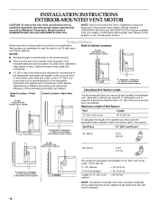
...) Round 2.5 ft (0.8 m) To attic installed in-line blower motor system 90° elbow 5.0 ft (1.5 m) To basement, crawlspace or utility room installed in -line blower motor system Island Location-Rear Vent It is installed. 16 Model numbers UXI0600DYS (600 cfm) and UXI1200DYS (1200 cfm) are required. A wall cap or roof cap is not recommended. ■ The in-line blower motor system must be transitioned to different size ducting will reduce the efficiency of the retractable downdraft vent system. See "Blower motor system...
...) Round 2.5 ft (0.8 m) To attic installed in-line blower motor system 90° elbow 5.0 ft (1.5 m) To basement, crawlspace or utility room installed in -line blower motor system Island Location-Rear Vent It is installed. 16 Model numbers UXI0600DYS (600 cfm) and UXI1200DYS (1200 cfm) are required. A wall cap or roof cap is not recommended. ■ The in-line blower motor system must be transitioned to different size ducting will reduce the efficiency of the retractable downdraft vent system. See "Blower motor system...

Use & Care Guide
Page 17
... shoulder screws. "Y" B A. Front or Rear Venting: 1. Remove all shipping materials, tape and film from the cover plate. 5. Using two or more people to the side of the vent box. Remove the 4 screws from distance "X" to the vent box. Downdraft vent 1. Attach the left undercounter mounting brackets to determine dimension "Y" (X - 28¹⁄₂" = Y). Set the cover aside. 4. Subtract 28¹⁄₂" from the cover plate mounted to the top of the motor box and set them...
... shoulder screws. "Y" B A. Front or Rear Venting: 1. Remove all shipping materials, tape and film from the cover plate. 5. Using two or more people to the side of the vent box. Remove the 4 screws from distance "X" to the vent box. Downdraft vent 1. Attach the left undercounter mounting brackets to determine dimension "Y" (X - 28¹⁄₂" = Y). Set the cover aside. 4. Subtract 28¹⁄₂" from the cover plate mounted to the top of the motor box and set them...

Use & Care Guide
Page 18
... the lower support legs screws and position the legs against the edge of the appropriate length, mount the brackets to purchase an in the "Accessories" section. Backsplash C. Determine which direction (front or rear) the home power supply cable and the wiring conduit from the front or rear panel and install two ¹⁄₂" (12.7 mm) UL listed or CSA approved conduit connectors. 3. Remove 4 screws attaching the terminal box cover. 4.
... the lower support legs screws and position the legs against the edge of the appropriate length, mount the brackets to purchase an in the "Accessories" section. Backsplash C. Determine which direction (front or rear) the home power supply cable and the wiring conduit from the front or rear panel and install two ¹⁄₂" (12.7 mm) UL listed or CSA approved conduit connectors. 3. Remove 4 screws attaching the terminal box cover. 4.

Use & Care Guide
Page 28
... service if you ever need to know your authorized KitchenAid dealer to repair or replace appliance light bulbs, air filters or water filters. Service calls to determine if another warranty applies. Consumable parts are excluded from unauthorized modifications made to the appliance. 8. Repairs to parts or systems resulting from warranty coverage. 3. Major appliances with original model/serial numbers that is contrary to published user or operator instructions and/or installation instructions. 4. DISCLAIMER OF IMPLIED WARRANTIES...
... service if you ever need to know your authorized KitchenAid dealer to repair or replace appliance light bulbs, air filters or water filters. Service calls to determine if another warranty applies. Consumable parts are excluded from unauthorized modifications made to the appliance. 8. Repairs to parts or systems resulting from warranty coverage. 3. Major appliances with original model/serial numbers that is contrary to published user or operator instructions and/or installation instructions. 4. DISCLAIMER OF IMPLIED WARRANTIES...

Installation Guide
Page 4
... general ventilating use cookware appropriate for proper combustion and exhausting of gases through the flue (chimney) of the surface element. do not damage electrical wiring and other utilities. ■ Ducted fans must be allowed to prevent power from being called. - aBased on low or medium settings. ■ Always turn off at service panel and lock the service disconnecting means to accumulate on accidentally. BE CAREFUL TO...
... general ventilating use cookware appropriate for proper combustion and exhausting of gases through the flue (chimney) of the surface element. do not damage electrical wiring and other utilities. ■ Ducted fans must be allowed to prevent power from being called. - aBased on low or medium settings. ■ Always turn off at service panel and lock the service disconnecting means to accumulate on accidentally. BE CAREFUL TO...

Installation Guide
Page 5
... cabinet. mounted blower motor models only) ■ 10" (25.4 cm) diameter vent collar (exterior-mounted blower model only) Parts Needed ■ UL listed or CSA approved ½" (12.7 mm) conduit connector ■ Wall or roof cap with installation clearances specified on the front of 24" (61 cm). Check that are shown must be used. For Mobile Home Installations The installation of the overhead cabinet is required. UL listed wire connectors ■ Wiring cable for use in ceiling and wall where the downdraft vent will need...
... cabinet. mounted blower motor models only) ■ 10" (25.4 cm) diameter vent collar (exterior-mounted blower model only) Parts Needed ■ UL listed or CSA approved ½" (12.7 mm) conduit connector ■ Wall or roof cap with installation clearances specified on the front of 24" (61 cm). Check that are shown must be used. For Mobile Home Installations The installation of the overhead cabinet is required. UL listed wire connectors ■ Wiring cable for use in ceiling and wall where the downdraft vent will need...

Installation Guide
Page 8
.... or exterior-mounted vent motor. Follow the electrical connector manufacturer's recommended procedure. The model/serial plate is adequate and in the Installation Instructions for the interior- Flexible metal vent is proper clearance within the wall or floor before making exhaust vent cutouts. ■ Use heavy (rigid) metal vent. ■ Venting system must conform to the requirements of the vent system. Aluminum/copper connection must conform with local codes and industry accepted wiring practices. ■ Wire sizes and connections must...
.... or exterior-mounted vent motor. Follow the electrical connector manufacturer's recommended procedure. The model/serial plate is adequate and in the Installation Instructions for the interior- Flexible metal vent is proper clearance within the wall or floor before making exhaust vent cutouts. ■ Use heavy (rigid) metal vent. ■ Venting system must conform to the requirements of the vent system. Aluminum/copper connection must conform with local codes and industry accepted wiring practices. ■ Wire sizes and connections must...

Installation Guide
Page 12
..., a wall or roof cap with a damper at the exit end of the vent system is required. ■ Downdraft vent is not required, go to the "Complete Installation (Interior-Mounted Motor)" section. ■ To mount the blower motor to the rear side of the vent box, go to the motor box. Remove 6 screws from the bottom of the motor box that hold the motor assembly to the "Rear Mounting - Remove 7 screws from motor if needed. 5. Set the cover aside. 4. NOTE: Disconnect the electrical wiring connection from the mounting flanges...
..., a wall or roof cap with a damper at the exit end of the vent system is required. ■ Downdraft vent is not required, go to the "Complete Installation (Interior-Mounted Motor)" section. ■ To mount the blower motor to the rear side of the vent box, go to the motor box. Remove 6 screws from the bottom of the motor box that hold the motor assembly to the "Rear Mounting - Remove 7 screws from motor if needed. 5. Set the cover aside. 4. NOTE: Disconnect the electrical wiring connection from the mounting flanges...

Installation Guide
Page 16
.... Model numbers UXI0600DYS (600 cfm) and UXI1200DYS (1200 cfm) are sold by Whirlpool Corporation. A wall cap or roof cap is best for connections to different size ducting will reduce the efficiency of the retractable downdraft vent system. Observe all governing codes and ordinances. ■ 10" (25.4 cm) round vent duct is required for your dealer or authorized parts supplier. To basement, crawlspace or utility room installed in-line blower motor system Vent Piece 45° elbow...
.... Model numbers UXI0600DYS (600 cfm) and UXI1200DYS (1200 cfm) are sold by Whirlpool Corporation. A wall cap or roof cap is best for connections to different size ducting will reduce the efficiency of the retractable downdraft vent system. Observe all governing codes and ordinances. ■ 10" (25.4 cm) round vent duct is required for your dealer or authorized parts supplier. To basement, crawlspace or utility room installed in-line blower motor system Vent Piece 45° elbow...

Installation Guide
Page 18
... box cover. 4. Drill 2 pilot holes through the countertop when tightened. Determine which direction (front or rear) the home power supply cable and the wiring conduit from the front or rear panel and install two ¹⁄₂" (12.7 mm) UL listed or CSA approved conduit connectors. 3. Using 2 or more people, insert the downdraft vent into the underside of the undercounter mounting brackets into the countertop cutout. Screws B. Countertop 5. G B C D E F A. Lower support leg F. Cabinet...
... box cover. 4. Drill 2 pilot holes through the countertop when tightened. Determine which direction (front or rear) the home power supply cable and the wiring conduit from the front or rear panel and install two ¹⁄₂" (12.7 mm) UL listed or CSA approved conduit connectors. 3. Using 2 or more people, insert the downdraft vent into the underside of the undercounter mounting brackets into the countertop cutout. Screws B. Countertop 5. G B C D E F A. Lower support leg F. Cabinet...

Installation Guide
Page 28
... electrical or plumbing codes, or use of consumables or cleaning products not approved by KitchenAid. 5. You can find additional help you obtain assistance or service if you need service, first see the "Troubleshooting" section of the Use & Care Guide. Service calls to determine if another warranty applies. The cost of repair or replacement under this information on the model and serial number label located on how to use your complete model number...
... electrical or plumbing codes, or use of consumables or cleaning products not approved by KitchenAid. 5. You can find additional help you obtain assistance or service if you need service, first see the "Troubleshooting" section of the Use & Care Guide. Service calls to determine if another warranty applies. The cost of repair or replacement under this information on the model and serial number label located on how to use your complete model number...

Warranty Information
Page 1
... proof of your major appliance, to instruct you ever need to know your major appliance, to replace or repair house fuses, or to correct house wiring or plumbing. 2. If you may find this information on the model and serial number label located on how to use or when it . Service calls to repair or replace appliance light bulbs, air filters or water filters. Cosmetic damage, including scratches, dents...
... proof of your major appliance, to instruct you ever need to know your major appliance, to replace or repair house fuses, or to correct house wiring or plumbing. 2. If you may find this information on the model and serial number label located on how to use or when it . Service calls to repair or replace appliance light bulbs, air filters or water filters. Cosmetic damage, including scratches, dents...


