Use & Care Guide
Page 1
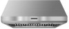
...CANOPY RANGE HOOD Installation Instructions and Use & Care Guide For questions about features, operation/performance, parts, accessories or service, call: 1-800-422-1230 or visit our website at www.kitchenaid.com In Canada, for assistance, installation and service, call: 1-800-807-6777 or visit ...utilisation et d'entretien Au Canada, pour assistance, installation ou service composez le 1-800-807-6777 ou visitez notre site web à www.kitchenaid.ca Table of Contents/Table des matières 2 IMPORTANT: READ AND SAVE THESE INSTRUCTIONS. IMPORTANT : LIRE ET CONSERVER CES INSTRUCTIONS. FOR...
...CANOPY RANGE HOOD Installation Instructions and Use & Care Guide For questions about features, operation/performance, parts, accessories or service, call: 1-800-422-1230 or visit our website at www.kitchenaid.com In Canada, for assistance, installation and service, call: 1-800-807-6777 or visit ...utilisation et d'entretien Au Canada, pour assistance, installation ou service composez le 1-800-807-6777 ou visitez notre site web à www.kitchenaid.ca Table of Contents/Table des matières 2 IMPORTANT: READ AND SAVE THESE INSTRUCTIONS. IMPORTANT : LIRE ET CONSERVER CES INSTRUCTIONS. FOR...

Use & Care Guide
Page 2
... instructions. We have provided many important safety messages in this manual and on your appliance. TABLE OF CONTENTS RANGE HOOD SAFETY 2 INSTALLATION REQUIREMENTS 3 Tools and Parts 3 Location Requirements 4 Venting Requirements 5 Electrical Requirements 6 INSTALLATION INSTRUCTIONS 7 Prepare Location 7 Install Range Hood 8 Install Range Hood Internal Blower Motor 8 Install Range Hood In-Line (External...
... instructions. We have provided many important safety messages in this manual and on your appliance. TABLE OF CONTENTS RANGE HOOD SAFETY 2 INSTALLATION REQUIREMENTS 3 Tools and Parts 3 Location Requirements 4 Venting Requirements 5 Electrical Requirements 6 INSTALLATION INSTRUCTIONS 7 Prepare Location 7 Install Range Hood 8 Install Range Hood Internal Blower Motor 8 Install Range Hood In-Line (External...
Use & Care Guide
Page 3
... turn off at service panel and lock the service disconnecting means to an exit. READ AND SAVE THESE INSTRUCTIONS INSTALLATION REQUIREMENTS Tools and Parts Gather the required tools and parts before starting installation. Heat oils slowly on accidentally. Read and follow the instructions provided with your back to prevent power from being...
... turn off at service panel and lock the service disconnecting means to an exit. READ AND SAVE THESE INSTRUCTIONS INSTALLATION REQUIREMENTS Tools and Parts Gather the required tools and parts before starting installation. Heat oils slowly on accidentally. Read and follow the instructions provided with your back to prevent power from being...
Use & Care Guide
Page 4
...halogen lamps installed. ■ 1 - 10" (25.4 cm) square to the Manufactured Home Construction Safety Standards, Title 24 CFR, Part 328 (formerly the Federal Standard for Manufactured Home Installation 1982 (Manufactured Home Sites, Communities and Setups) ANSI A225.1/NFPA 501A*, or latest...50 mm wall anchors ■ T-20 TORX®† adapter Location Requirements IMPORTANT: Observe all parts are shown must be used. All openings in the "Accessories" section.) Parts supplied Remove parts from strong draft areas, such as windows, doors and strong heating vents. Wood support D. ...
...halogen lamps installed. ■ 1 - 10" (25.4 cm) square to the Manufactured Home Construction Safety Standards, Title 24 CFR, Part 328 (formerly the Federal Standard for Manufactured Home Installation 1982 (Manufactured Home Sites, Communities and Setups) ANSI A225.1/NFPA 501A*, or latest...50 mm wall anchors ■ T-20 TORX®† adapter Location Requirements IMPORTANT: Observe all parts are shown must be used. All openings in the "Accessories" section.) Parts supplied Remove parts from strong draft areas, such as windows, doors and strong heating vents. Wood support D. ...
Use & Care Guide
Page 5
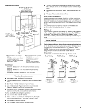
... of canopy to cooking surface 13" (33.0 cm) ■ The vent system must terminate to provide efficient performance. The break should be as close as part of the vent system. Roof Venting Wall Venting Wall Venting A B A B B A Venting Requirements ■ Vent system must have a damper. Roof cap B. 10" (25.4 cm) round vent...
... of canopy to cooking surface 13" (33.0 cm) ■ The vent system must terminate to provide efficient performance. The break should be as close as part of the vent system. Roof Venting Wall Venting Wall Venting A B A B B A Venting Requirements ■ Vent system must have a damper. Roof cap B. 10" (25.4 cm) round vent...

Use & Care Guide
Page 6
...Length To calculate the length of the National Electrical Code, ANSI/NFPA 70 (latest edition), or CSA Standards C22. 1-94, Canadian Electrical Code, Part 1 and C22.2 No. 0-M91 (latest edition) and all local codes and ordinances. Connect the aluminum wiring to the added section of the.... ■ Wire sizes must conform with National Electrical Code, ANSI/NFPA 70 (latest edition), or CSA Standards C22.1-94, Canadian Electrical Code, Part 1 and C22.2 No. 0-M91 (latest edition) and all governing codes and ordinances. Aluminum/copper connection must conform with local codes and industry ...
...Length To calculate the length of the National Electrical Code, ANSI/NFPA 70 (latest edition), or CSA Standards C22. 1-94, Canadian Electrical Code, Part 1 and C22.2 No. 0-M91 (latest edition) and all local codes and ordinances. Connect the aluminum wiring to the added section of the.... ■ Wire sizes must conform with National Electrical Code, ANSI/NFPA 70 (latest edition), or CSA Standards C22.1-94, Canadian Electrical Code, Part 1 and C22.2 No. 0-M91 (latest edition) and all governing codes and ordinances. Aluminum/copper connection must conform with local codes and industry ...
Use & Care Guide
Page 7
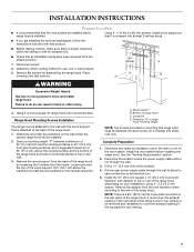
... least 2 vertical studs. ■ If you are installing the optional backsplash, follow the instructions included with that product. ■ Before making cutouts, make all installation parts have been removed from gas cooking surfaces, and a suggested maximum of the range hood for top venting or be removed and reinstalled to move and...
... least 2 vertical studs. ■ If you are installing the optional backsplash, follow the instructions included with that product. ■ Before making cutouts, make all installation parts have been removed from gas cooking surfaces, and a suggested maximum of the range hood for top venting or be removed and reinstalled to move and...

Use & Care Guide
Page 8
... the rear panel of mounting holes for the selected motor system. For top venting, the mounting bracket and spring clip that are blower motor mounting parts in the panel and secure with clamps. See the "Range Hood Care" section in the "Accessories" section. Screw bracket to the horizontal line, level the...
... the rear panel of mounting holes for the selected motor system. For top venting, the mounting bracket and spring clip that are blower motor mounting parts in the panel and secure with clamps. See the "Range Hood Care" section in the "Accessories" section. Screw bracket to the horizontal line, level the...
Use & Care Guide
Page 12
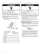
... green (or yellow/green) ground wire to do so can result in the "Prepare Location" section). 4. I . Red wires F. Tighten the strain relief screws. 5. Replace all parts and panels before servicing. Electrical Connection Inside In-line Blower System 1. Connect ground wire to do so can result in death or electrical shock. With...
... green (or yellow/green) ground wire to do so can result in the "Prepare Location" section). 4. I . Red wires F. Tighten the strain relief screws. 5. Replace all parts and panels before servicing. Electrical Connection Inside In-line Blower System 1. Connect ground wire to do so can result in death or electrical shock. With...

Use & Care Guide
Page 13
... UL listed wire connectors and connect white wires (A) together. Failure to do so can result in death or electrical shock. Disconnect power. 2. Check that all parts and panels before servicing. Knockout in terminal box. NOTE: When using UL listed wire connectors (see the "Make Electrical Power Supply Connections to the green...
... UL listed wire connectors and connect white wires (A) together. Failure to do so can result in death or electrical shock. Disconnect power. 2. Check that all parts and panels before servicing. Knockout in terminal box. NOTE: When using UL listed wire connectors (see the "Make Electrical Power Supply Connections to the green...
Use & Care Guide
Page 17
... assistance, you can write to KitchenAid with solid shelf) Order Part Number W10225950 for 30" (76.2 cm) models Order Part Number W10225949 for 36" (91.4 cm) models Order Part Number W10225948 for 48" (121.9 cm) models To locate the KitchenAid designated service company in your area... trained to local dealers, repair parts distributors and service companies. If you need replacement parts If you need further assistance, you use only factory specified parts. Order Model Number UXB1200DYS 600 CFM In-Line Blower Motor System - Call the KitchenAid Customer eXperience Center toll free: ...
... assistance, you can write to KitchenAid with solid shelf) Order Part Number W10225950 for 30" (76.2 cm) models Order Part Number W10225949 for 36" (91.4 cm) models Order Part Number W10225948 for 48" (121.9 cm) models To locate the KitchenAid designated service company in your area... trained to local dealers, repair parts distributors and service companies. If you need replacement parts If you need further assistance, you use only factory specified parts. Order Model Number UXB1200DYS 600 CFM In-Line Blower Motor System - Call the KitchenAid Customer eXperience Center toll free: ...
Use & Care Guide
Page 18
...calls to the appliance. 8. Cosmetic damage, including scratches, dents, chips or other than normal, single-family household use your authorized KitchenAid dealer to determine if another warranty applies. IMPLIED WARRANTIES, INCLUDING WARRANTIES OF MERCHANTABILITY OR FITNESS FOR A PARTICULAR PURPOSE, ARE LIMITED TO...warranty service. The removal and reinstallation of your major appliance is reported to KitchenAid within 30 days from the date of purchase or installation date for Factory Specified Parts and repair labor to correct defects in materials or workmanship and is located in...
...calls to the appliance. 8. Cosmetic damage, including scratches, dents, chips or other than normal, single-family household use your authorized KitchenAid dealer to determine if another warranty applies. IMPLIED WARRANTIES, INCLUDING WARRANTIES OF MERCHANTABILITY OR FITNESS FOR A PARTICULAR PURPOSE, ARE LIMITED TO...warranty service. The removal and reinstallation of your major appliance is reported to KitchenAid within 30 days from the date of purchase or installation date for Factory Specified Parts and repair labor to correct defects in materials or workmanship and is located in...

Installation Guide
Page 1
...) COMMERCIAL STYLE WALL-MOUNT CANOPY RANGE HOOD Installation Instructions and Use & Care Guide For questions about features, operation/performance, parts, accessories or service, call: 1-800-422-1230 or visit our website at www.kitchenaid.com In Canada, for assistance, installation and service, call: 1-800-807-6777 or visit our website at www....kitchenaid.ca HOTTE DE CUISINIÈRE DE STYLE COMMERCIAL POUR MONTAGE MURAL 30", 36" ET 48" (76,2 CM, 91,4 CM ET 121,9 CM) Instructions d'installation ...
...) COMMERCIAL STYLE WALL-MOUNT CANOPY RANGE HOOD Installation Instructions and Use & Care Guide For questions about features, operation/performance, parts, accessories or service, call: 1-800-422-1230 or visit our website at www.kitchenaid.com In Canada, for assistance, installation and service, call: 1-800-807-6777 or visit our website at www....kitchenaid.ca HOTTE DE CUISINIÈRE DE STYLE COMMERCIAL POUR MONTAGE MURAL 30", 36" ET 48" (76,2 CM, 91,4 CM ET 121,9 CM) Instructions d'installation ...
Installation Guide
Page 2
These words mean: DANGER You can kill or hurt you don't immediately follow instructions. TABLE OF CONTENTS RANGE HOOD SAFETY 2 INSTALLATION REQUIREMENTS 3 Tools and Parts 3 Location Requirements 4 Venting Requirements 5 Electrical Requirements 6 INSTALLATION INSTRUCTIONS 7 Prepare Location 7 Install Range Hood 8 Install Range Hood Internal Blower Motor 8 Install Range Hood In-Line (External ...
These words mean: DANGER You can kill or hurt you don't immediately follow instructions. TABLE OF CONTENTS RANGE HOOD SAFETY 2 INSTALLATION REQUIREMENTS 3 Tools and Parts 3 Location Requirements 4 Venting Requirements 5 Electrical Requirements 6 INSTALLATION INSTRUCTIONS 7 Prepare Location 7 Install Range Hood 8 Install Range Hood Internal Blower Motor 8 Install Range Hood In-Line (External ...

Installation Guide
Page 3
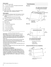
... dishcloths or towels a violent steam explosion will result. ■ Use an extinguisher ONLY if: - READ AND SAVE THESE INSTRUCTIONS INSTALLATION REQUIREMENTS Tools and Parts Gather the required tools and parts before starting installation. The fire department is needed ■ Level ■ Drill ■ 1¼" (3 cm) drill bit 3 mm) drill bit if installing...
... dishcloths or towels a violent steam explosion will result. ■ Use an extinguisher ONLY if: - READ AND SAVE THESE INSTRUCTIONS INSTALLATION REQUIREMENTS Tools and Parts Gather the required tools and parts before starting installation. The fire department is needed ■ Level ■ Drill ■ 1¼" (3 cm) drill bit 3 mm) drill bit if installing...

Installation Guide
Page 4
... A. Top of the range hood. Canopy range hood location should be sealed. Knockout into terminal box B. Have a qualified technician install the range hood. Parts needed ■ Home power supply cable ■ 1 - ½" (12.7 mm) UL listed or CSA approved strain relief ■ 3 UL ...9632; 1 wall or roof cap ■ Metal vent system ■ Blower motor system - All openings in the "Accessories" section.) Parts supplied Remove parts from strong draft areas, such as windows, doors and strong heating vents. internal or external (See "Blower Motor System" in ceiling and...
... A. Top of the range hood. Canopy range hood location should be sealed. Knockout into terminal box B. Have a qualified technician install the range hood. Parts needed ■ Home power supply cable ■ 1 - ½" (12.7 mm) UL listed or CSA approved strain relief ■ 3 UL ...9632; 1 wall or roof cap ■ Metal vent system ■ Blower motor system - All openings in the "Accessories" section.) Parts supplied Remove parts from strong draft areas, such as windows, doors and strong heating vents. internal or external (See "Blower Motor System" in ceiling and...

Installation Guide
Page 5
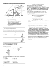
... to seal exterior wall or roof opening is not recommended. ■ The length of vent system and number of elbows should be as close as part of outside temperatures as possible to minimize backward cold air flow and a thermal break should be uniform. Venting Methods 36" (91.4 cm) countertop height A. The...
... to seal exterior wall or roof opening is not recommended. ■ The length of vent system and number of elbows should be as close as part of outside temperatures as possible to minimize backward cold air flow and a thermal break should be uniform. Venting Methods 36" (91.4 cm) countertop height A. The...
Installation Guide
Page 6
... for joining copper to the added section of the National Electrical Code, ANSI/NFPA 70 (latest edition), or CSA Standards C22. 1-94, Canadian Electrical Code, Part 1 and C22.2 No. 0-M91 (latest edition) and all local codes and ordinances. H. Connect a section of system = 13.0 ft (3.9 m) 6 wall cap = 5.0 ft (1.5 m) =...used in conformance with National Electrical Code, ANSI/NFPA 70 (latest edition), or CSA Standards C22.1-94, Canadian Electrical Code, Part 1 and C22.2 No. 0-M91 (latest edition) and all governing codes and ordinances. Aluminum/copper connection must conform with local...
... for joining copper to the added section of the National Electrical Code, ANSI/NFPA 70 (latest edition), or CSA Standards C22. 1-94, Canadian Electrical Code, Part 1 and C22.2 No. 0-M91 (latest edition) and all local codes and ordinances. H. Connect a section of system = 13.0 ft (3.9 m) 6 wall cap = 5.0 ft (1.5 m) =...used in conformance with National Electrical Code, ANSI/NFPA 70 (latest edition), or CSA Standards C22.1-94, Canadian Electrical Code, Part 1 and C22.2 No. 0-M91 (latest edition) and all governing codes and ordinances. Aluminum/copper connection must conform with local...

Installation Guide
Page 7
... least 2 vertical studs. ■ If you are installing the optional backsplash, follow the instructions included with that product. ■ Before making cutouts, make all installation parts have been removed from the vent transition when mounting to do not fasten into solid wood; Select a flat surface for exhaust vent. ■ Check that...
... least 2 vertical studs. ■ If you are installing the optional backsplash, follow the instructions included with that product. ■ Before making cutouts, make all installation parts have been removed from the vent transition when mounting to do not fasten into solid wood; Select a flat surface for exhaust vent. ■ Check that...

Installation Guide
Page 8
... outside set of the range hood and install a UL listed or CSA approved ¹⁄₂" (1.3 cm) strain relief. 8. If holes are blower motor mounting parts in the range hood back over the 2 screws mounted to the wood support mounted to the wall in the "Accessories" section. For information on the...
... outside set of the range hood and install a UL listed or CSA approved ¹⁄₂" (1.3 cm) strain relief. 8. If holes are blower motor mounting parts in the range hood back over the 2 screws mounted to the wood support mounted to the wall in the "Accessories" section. For information on the...