Dimension Guide
Page 1
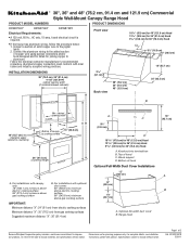
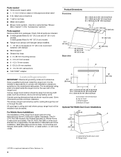
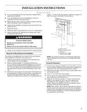
... (45.7 cm) A B Because Whirlpool Corporation policy includes a continuous commitment to improve Dimensions are for 30" (76.2 cm) Hood A. For installations with optional duct cover: 90" (228.6 cm) minimum above electric cooking surface 96" (243.8 cm) minimum above gas cooking surface B. W10331007B ... and industry accepted wiring practices. clearance upper cabinet to change materials and specifications without notice. Page 1 of hood Optional Full-Width Duct Cover Installations 12" (30.5 cm) 12" (30.5 cm) 18" (45.7 cm) A. q If the house has aluminum wiring, follow the...
... (45.7 cm) A B Because Whirlpool Corporation policy includes a continuous commitment to improve Dimensions are for 30" (76.2 cm) Hood A. For installations with optional duct cover: 90" (228.6 cm) minimum above electric cooking surface 96" (243.8 cm) minimum above gas cooking surface B. W10331007B ... and industry accepted wiring practices. clearance upper cabinet to change materials and specifications without notice. Page 1 of hood Optional Full-Width Duct Cover Installations 12" (30.5 cm) 12" (30.5 cm) 18" (45.7 cm) A. q If the house has aluminum wiring, follow the...
Dimension Guide
Page 2
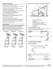
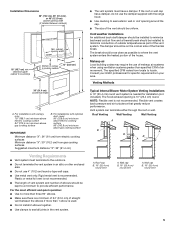
... - The hood exhaust opening around the cap. NOTE: Flexible vent is not recommended. Plywood (optional for installation (not included). Mount from cross-members tied to trusses. G. H. q Do not install 2 elbows together. q The size of the system you need, add the equivalent feet (meters) for ...planning purposes only. Venting Methods Typical Internal Blower Motor System Venting Installations A 10" (25.4 cm) round vent system is needed for some installations) E. Wall cap Calculating Vent System Length To calculate the length of the vent should...
... - The hood exhaust opening around the cap. NOTE: Flexible vent is not recommended. Plywood (optional for installation (not included). Mount from cross-members tied to trusses. G. H. q Do not install 2 elbows together. q The size of the system you need, add the equivalent feet (meters) for ...planning purposes only. Venting Methods Typical Internal Blower Motor System Venting Installations A 10" (25.4 cm) round vent system is needed for some installations) E. Wall cap Calculating Vent System Length To calculate the length of the vent should...
Use & Care Guide
Page 1
..., parts, accessories or service, call: 1-800-422-1230 or visit our website at www.kitchenaid.com In Canada, for assistance, installation and service, call: 1-800-807-6777 or visit our website at www.kitchenaid.ca HOTTE DE CUISINIÈRE DE STYLE COMMERCIAL POUR MONTAGE MURAL 30", 36" ET 48..." (76,2 CM, 91,4 CM ET 121,9 CM) Instructions d'installation et Guide d'utilisation et d'entretien Au Canada, pour assistance, installation ou service composez le 1-800-807-6777 ou visitez notre site web à www.kitchenaid.ca Table of Contents/Table des matières 2 IMPORTANT: READ AND SAVE ...
..., parts, accessories or service, call: 1-800-422-1230 or visit our website at www.kitchenaid.com In Canada, for assistance, installation and service, call: 1-800-807-6777 or visit our website at www.kitchenaid.ca HOTTE DE CUISINIÈRE DE STYLE COMMERCIAL POUR MONTAGE MURAL 30", 36" ET 48..." (76,2 CM, 91,4 CM ET 121,9 CM) Instructions d'installation et Guide d'utilisation et d'entretien Au Canada, pour assistance, installation ou service composez le 1-800-807-6777 ou visitez notre site web à www.kitchenaid.ca Table of Contents/Table des matières 2 IMPORTANT: READ AND SAVE ...

Use & Care Guide
Page 2
... in this manual and on your appliance. Always read and obey all safety messages. This is , tell you how to Range Hood .....13 Complete Installation and Check Operation 14 RANGE HOOD USE 14 Range Hood Controls 14 RANGE HOOD CARE 15 Range Hood Lamps 15 Cleaning 15 WIRING DIAGRAM 16...des connexions électriques du système du moteur du ventilateur en ligne 30 Connexion de l'alimentation électrique à la hotte 31 Achever l'installation et vérifier le fonctionnement 32 UTILISATION DE LA HOTTE 32 Commandes de la hotte de cuisinière 32 ENTRETIEN DE LA HOTTE DE...
... in this manual and on your appliance. Always read and obey all safety messages. This is , tell you how to Range Hood .....13 Complete Installation and Check Operation 14 RANGE HOOD USE 14 Range Hood Controls 14 RANGE HOOD CARE 15 Range Hood Lamps 15 Cleaning 15 WIRING DIAGRAM 16...des connexions électriques du système du moteur du ventilateur en ligne 30 Connexion de l'alimentation électrique à la hotte 31 Achever l'installation et vérifier le fonctionnement 32 UTILISATION DE LA HOTTE 32 Commandes de la hotte de cuisinière 32 ENTRETIEN DE LA HOTTE DE...
Use & Care Guide
Page 3
...repair. ■ Sufficient air is needed ■ Level ■ Drill ■ 1¼" (3 cm) drill bit 3 mm) drill bit if installing into crawl spaces, or garages. Follow the heating equipment manufacturer's guideline and safety standards such as a tag, to prevent backdrafting. do not use ...When cutting or drilling into wall or ceiling; Tools needed for the size of fuel burning equipment to the service panel. ■ Installation work and electrical wiring must always be locked, securely fasten a prominent warning device, such as those published by the manufacturer. Do not...
...repair. ■ Sufficient air is needed ■ Level ■ Drill ■ 1¼" (3 cm) drill bit 3 mm) drill bit if installing into crawl spaces, or garages. Follow the heating equipment manufacturer's guideline and safety standards such as a tag, to prevent backdrafting. do not use ...When cutting or drilling into wall or ceiling; Tools needed for the size of fuel burning equipment to the service panel. ■ Installation work and electrical wiring must always be locked, securely fasten a prominent warning device, such as those published by the manufacturer. Do not...
Use & Care Guide
Page 4
... 24, HUD, Part 280) or when such standard is not applicable, the standard for 48" (121.9 cm) models ■ Range hood canopy with halogen lamps installed. ■ 1 - 10" (25.4 cm) square to comply with damper ■ Wood support ■ Grease drip trays ■ 4 - 6 x 80 mm ...mounting screws ■ 4 - 3.5 x 9.5 mm screws ■ 6 - 4.2 x 19 mm screws ■ 2 - For Mobile Home Installations The installation of hood Optional Full-Width Duct Cover Installations 12" (30.5 cm) 12" (30.5 cm) 18" (45.7 cm) 18" (45.7 cm) A B A. Range hood †®TORX is located ...
... 24, HUD, Part 280) or when such standard is not applicable, the standard for 48" (121.9 cm) models ■ Range hood canopy with halogen lamps installed. ■ 1 - 10" (25.4 cm) square to comply with damper ■ Wood support ■ Grease drip trays ■ 4 - 6 x 80 mm ...mounting screws ■ 4 - 3.5 x 9.5 mm screws ■ 6 - 4.2 x 19 mm screws ■ 2 - For Mobile Home Installations The installation of hood Optional Full-Width Duct Cover Installations 12" (30.5 cm) 12" (30.5 cm) 18" (45.7 cm) 18" (45.7 cm) A B A. Range hood †®TORX is located ...
Use & Care Guide
Page 5
...the vent system. The specified CFM varies from gas cooking surfaces Suggested maximum distance "X": 36" (91.4 cm) Typical Internal Blower Motor System Venting Installations A 10" (25.4 cm) round vent system is not recommended. ■ The length of vent system and number of elbows should be ...Makeup air Local building codes may require the use 4" (10.2 cm) laundry-type wall caps. ■ Use metal vent only. For installations with the range hood. ■ Use caulking to minimize conduction of outside temperatures as possible to provide efficient performance. The hood exhaust opening is...
...the vent system. The specified CFM varies from gas cooking surfaces Suggested maximum distance "X": 36" (91.4 cm) Typical Internal Blower Motor System Venting Installations A 10" (25.4 cm) round vent system is not recommended. ■ The length of vent system and number of elbows should be ...Makeup air Local building codes may require the use 4" (10.2 cm) laundry-type wall caps. ■ Use metal vent only. For installations with the range hood. ■ Use caulking to minimize conduction of outside temperatures as possible to provide efficient performance. The hood exhaust opening is...
Use & Care Guide
Page 6
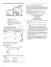
.../or tools designed and UL listed for each vent piece used , it is recommended that a qualified electrician determine that the electrical installation is required. ■ If the house has aluminum wiring, follow the procedure below: 1. Connect the aluminum wiring to the added... the appliance as specified on top of solid copper wire to trusses. The model/serial plate is adequate. Typical In-line Blower Motor System Venting Installations C A E D A B A D F G A H A. 10" (25.4 cm) round vent B. Mount from : National Fire Protection Association One Batterymarch Park Quincy, MA ...
.../or tools designed and UL listed for each vent piece used , it is recommended that a qualified electrician determine that the electrical installation is required. ■ If the house has aluminum wiring, follow the procedure below: 1. Connect the aluminum wiring to the added... the appliance as specified on top of solid copper wire to trusses. The model/serial plate is adequate. Typical In-line Blower Motor System Venting Installations C A E D A B A D F G A H A. 10" (25.4 cm) round vent B. Mount from : National Fire Protection Association One Batterymarch Park Quincy, MA ...
Use & Care Guide
Page 7
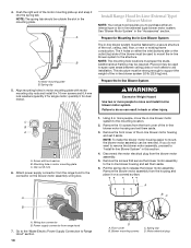
... range hood. do so can result in back or other injury. 4. Complete Preparation 1. Determine the location where the power supply cable will be installed. 2. Locate and level the top of the wood support 15³⁄₈" (39.1 cm) above the cooking surface and the bottom of... to allow for assembling the range hood. D WARNING Excessive Weight Hazard Use two or more people, lift range hood onto covered surface. INSTALLATION INSTRUCTIONS Prepare Location ■ It is recommended that it is screwed into at this range hood must cover the exhaust opening in the rear...
... range hood. do so can result in back or other injury. 4. Complete Preparation 1. Determine the location where the power supply cable will be installed. 2. Locate and level the top of the wood support 15³⁄₈" (39.1 cm) above the cooking surface and the bottom of... to allow for assembling the range hood. D WARNING Excessive Weight Hazard Use two or more people, lift range hood onto covered surface. INSTALLATION INSTRUCTIONS Prepare Location ■ It is recommended that it is screwed into at this range hood must cover the exhaust opening in the rear...

Use & Care Guide
Page 8
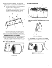
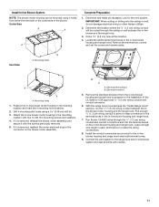
... top panel of mounting holes for the dual motor system. Motor support bracket D. Tighten the strain relief screws. See the "Install Range Hood Internal Blower Motor" section and the instructions supplied with the screws. Prepare the Internal Blower System IMPORTANT: Perform steps...cm) strain relief. 8. For top venting, the mounting bracket and spring clip that are blower motor mounting parts in the "Range Hood Mounting Screws Installation" section. 1. B A → → 2. Place the range hood near its mounting position and run the power supply cable through the ...
... top panel of mounting holes for the dual motor system. Motor support bracket D. Tighten the strain relief screws. See the "Install Range Hood Internal Blower Motor" section and the instructions supplied with the screws. Prepare the Internal Blower System IMPORTANT: Perform steps...cm) strain relief. 8. For top venting, the mounting bracket and spring clip that are blower motor mounting parts in the "Range Hood Mounting Screws Installation" section. 1. B A → → 2. Place the range hood near its mounting position and run the power supply cable through the ...
Use & Care Guide
Page 9
...A A A. Motor mounting plate hole B. Power supply wires and connector 9 A ■ Two 6 mm nuts are required for the selected motor system. Install the range hood blower motor assembly inside the range hood canopy with the wiring connection to the left and right end of the square vent ...opening . ■ Five 6 mm nuts are required for dual motor assembly (quantity 5) B. Motor mounting bracket B. Install the 6 mm nuts to the front or top for single motor assembly (quantity 2) 5. Run the power supply wires and connector from the range hood...
...A A A. Motor mounting plate hole B. Power supply wires and connector 9 A ■ Two 6 mm nuts are required for the selected motor system. Install the range hood blower motor assembly inside the range hood canopy with the wiring connection to the left and right end of the square vent ...opening . ■ Five 6 mm nuts are required for dual motor assembly (quantity 5) B. Motor mounting bracket B. Install the 6 mm nuts to the front or top for single motor assembly (quantity 2) 5. Run the power supply wires and connector from the range hood...
Use & Care Guide
Page 10
... fastened to support the weight of the roof, ceiling, wall, floor, or new or existing frame construction. Screw with motor mounting clip nuts and install 6 x 16 mm screws and 6.4 mm lock washers (quantity 2 for dual motor). Remove the screws that secure the blower motor assembly to release...Wiring box connector B. Blower mounting screws C. Prepare the In-line Blower System WARNING Excessive Weight Hazard Use two or more people, move and install in back or other injury. Attach power supply connector from the range hood to do not want to remove the blower motor assembly, proceed to...
... fastened to support the weight of the roof, ceiling, wall, floor, or new or existing frame construction. Screw with motor mounting clip nuts and install 6 x 16 mm screws and 6.4 mm lock washers (quantity 2 for dual motor). Remove the screws that secure the blower motor assembly to release...Wiring box connector B. Blower mounting screws C. Prepare the In-line Blower System WARNING Excessive Weight Hazard Use two or more people, move and install in back or other injury. Attach power supply connector from the range hood to do not want to remove the blower motor assembly, proceed to...
Use & Care Guide
Page 11
...housing and range hood electrical terminal boxes. 9. Connect the vent system to the in -line blower system and seal all necessary cuts for the installation of the blower. Drill a 1¹⁄₄" (3.2 cm) hole at this location. 4. Locate the electrical terminal boxes in the in its... using a 0.48 cm) drill bit. 3. Drill 4 mounting pilot holes using 4 holes from the in -line blower housing and range hood. B A A. Install In-line Blower System NOTE: The blower motor housing can be routed through the ¹⁄₂" (1.3 cm) wiring conduit and conduit connectors and into...
...housing and range hood electrical terminal boxes. 9. Connect the vent system to the in -line blower system and seal all necessary cuts for the installation of the blower. Drill a 1¹⁄₄" (3.2 cm) hole at this location. 4. Locate the electrical terminal boxes in the in its... using a 0.48 cm) drill bit. 3. Drill 4 mounting pilot holes using 4 holes from the in -line blower housing and range hood. B A A. Install In-line Blower System NOTE: The blower motor housing can be routed through the ¹⁄₂" (1.3 cm) wiring conduit and conduit connectors and into...
Use & Care Guide
Page 12
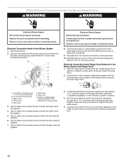
... wires from the wiring conduit to the wires from the motor electrical plug cable inside the range hood and install a ¹⁄₂" (1.3 cm) UL listed or CSA approved strain relief (see the "Install Range Hood" section), locate the wiring cable connector inside the range hood terminal box. 12 Black wires D. White...
... wires from the wiring conduit to the wires from the motor electrical plug cable inside the range hood and install a ¹⁄₂" (1.3 cm) UL listed or CSA approved strain relief (see the "Install Range Hood" section), locate the wiring cable connector inside the range hood terminal box. 12 Black wires D. White...

Use & Care Guide
Page 13
... ground wire in terminal box using UL listed wire connectors. 6. Connect ground wire to Range Hood WARNING Electrical Shock Hazard Electrically ground blower. Disconnect power. 2. Install terminal box cover. 7. Black wires D. Gray wires H. Green (or green/yellow) wire I E. Go to "Make Electrical Power Supply Connection to the green (or bare) ground...
... ground wire in terminal box using UL listed wire connectors. 6. Connect ground wire to Range Hood WARNING Electrical Shock Hazard Electrically ground blower. Disconnect power. 2. Install terminal box cover. 7. Black wires D. Gray wires H. Green (or green/yellow) wire I E. Go to "Make Electrical Power Supply Connection to the green (or bare) ground...

Use & Care Guide
Page 14
... from your new range hood, read the "Range Hood Use" section. When the heat decreases, the fan will turn range hood light OFF. A B C A. Complete Installation and Check Operation 1. Install grease filters. B A A C D E A. Halogen light switch C. Blower control switches D. Grease filter E. NOTE: To get the most efficient use , move slider to On to "1" position...
... from your new range hood, read the "Range Hood Use" section. When the heat decreases, the fan will turn range hood light OFF. A B C A. Complete Installation and Check Operation 1. Install grease filters. B A A C D E A. Halogen light switch C. Blower control switches D. Grease filter E. NOTE: To get the most efficient use , move slider to On to "1" position...
Use & Care Guide
Page 17
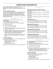
...) model Order Part Number W10272080 for 36" (91.4 cm) model Order Part Number W10272081 for 48" (121.9 cm) model ■ Installation information. ■ Use and maintenance procedures. ■ Accessory and repair parts sales. ■ Specialized customer assistance (Spanish speaking, hearing impaired... anywhere in your correspondence. 17 Accessories Blower Motor Systems (1 system is required) 600 CFM Internal Blower Motor System - KitchenAid designated service technicians are trained to local dealers, repair parts distributors and service companies. Backsplash Kit (without shelf) Order ...
...) model Order Part Number W10272080 for 36" (91.4 cm) model Order Part Number W10272081 for 48" (121.9 cm) model ■ Installation information. ■ Use and maintenance procedures. ■ Accessory and repair parts sales. ■ Specialized customer assistance (Spanish speaking, hearing impaired... anywhere in your correspondence. 17 Accessories Blower Motor Systems (1 system is required) 600 CFM Internal Blower Motor System - KitchenAid designated service technicians are trained to local dealers, repair parts distributors and service companies. Backsplash Kit (without shelf) Order ...
Use & Care Guide
Page 18
... major appliance is located in materials or workmanship. The removal and reinstallation of purchase or installation date for Factory Specified Parts and repair labor to better help by checking the "Assistance or Service" section or by a KitchenAid designated service company. Outside the 50 United States and Canada, this book and your major...
... major appliance is located in materials or workmanship. The removal and reinstallation of purchase or installation date for Factory Specified Parts and repair labor to better help by checking the "Assistance or Service" section or by a KitchenAid designated service company. Outside the 50 United States and Canada, this book and your major...

Installation Guide
Page 1
..., parts, accessories or service, call: 1-800-422-1230 or visit our website at www.kitchenaid.com In Canada, for assistance, installation and service, call: 1-800-807-6777 or visit our website at www.kitchenaid.ca HOTTE DE CUISINIÈRE DE STYLE COMMERCIAL POUR MONTAGE MURAL 30", 36" ET 48..." (76,2 CM, 91,4 CM ET 121,9 CM) Instructions d'installation et Guide d'utilisation et d'entretien Au Canada, pour assistance, installation ou service composez le 1-800-807-6777 ou visitez notre site web à www.kitchenaid.ca Table of Contents/Table des matières 2 IMPORTANT: READ AND SAVE ...
..., parts, accessories or service, call: 1-800-422-1230 or visit our website at www.kitchenaid.com In Canada, for assistance, installation and service, call: 1-800-807-6777 or visit our website at www.kitchenaid.ca HOTTE DE CUISINIÈRE DE STYLE COMMERCIAL POUR MONTAGE MURAL 30", 36" ET 48..." (76,2 CM, 91,4 CM ET 121,9 CM) Instructions d'installation et Guide d'utilisation et d'entretien Au Canada, pour assistance, installation ou service composez le 1-800-807-6777 ou visitez notre site web à www.kitchenaid.ca Table of Contents/Table des matières 2 IMPORTANT: READ AND SAVE ...

Installation Guide
Page 2
...) Blower Motor 10 Make Electrical Connections for In-Line Blower Motor System 12 Make Electrical Power Supply Connection to Range Hood .....13 Complete Installation and Check Operation 14 RANGE HOOD USE 14 Range Hood Controls 14 RANGE HOOD CARE 15 Range Hood Lamps 15 Cleaning 15 WIRING DIAGRAM 16...électriques du système du moteur du ventilateur en ligne 30 Connexion de l'alimentation électrique à la hotte 31 Achever l'installation et vérifier le fonctionnement 32 UTILISATION DE LA HOTTE 32 Commandes de la hotte de cuisinière 32 ENTRETIEN DE LA HOTTE DE...
...) Blower Motor 10 Make Electrical Connections for In-Line Blower Motor System 12 Make Electrical Power Supply Connection to Range Hood .....13 Complete Installation and Check Operation 14 RANGE HOOD USE 14 Range Hood Controls 14 RANGE HOOD CARE 15 Range Hood Lamps 15 Cleaning 15 WIRING DIAGRAM 16...électriques du système du moteur du ventilateur en ligne 30 Connexion de l'alimentation électrique à la hotte 31 Achever l'installation et vérifier le fonctionnement 32 UTILISATION DE LA HOTTE 32 Commandes de la hotte de cuisinière 32 ENTRETIEN DE LA HOTTE DE...
