Owners Manual
Page 1
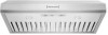
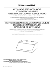
..." (76.2 CM) AND 36" (91.4 CM) COMMERCIAL STYLE WALL-MOUNT CANOPY RANGE HOOD Installation Instructions and Use & Care Guide For questions about features, operation/performance, parts, accessories or service, call: 1-800-422-1230 or visit our website at www.kitchenaid.com In Canada, for assistance, installation and service, call: 1-800-807-6777 or visit our website at www.kitchenaid.ca HOTTE D'EXTRACTION À MONTAGE MURAL DE STYLE COMMERCIAL DE 30...
..." (76.2 CM) AND 36" (91.4 CM) COMMERCIAL STYLE WALL-MOUNT CANOPY RANGE HOOD Installation Instructions and Use & Care Guide For questions about features, operation/performance, parts, accessories or service, call: 1-800-422-1230 or visit our website at www.kitchenaid.com In Canada, for assistance, installation and service, call: 1-800-807-6777 or visit our website at www.kitchenaid.ca HOTTE D'EXTRACTION À MONTAGE MURAL DE STYLE COMMERCIAL DE 30...
Owners Manual
Page 2
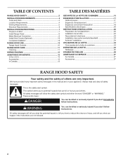
... mean: DANGER You can happen if the instructions are very important. TABLE OF CONTENTS RANGE HOOD SAFETY 2 INSTALLATION REQUIREMENTS 4 Tools and Parts 4 Location Requirements 4 Venting Requirements 5 Electrical Requirements 6 INSTALLATION INSTRUCTIONS 7 Prepare Location 7 Install Range Hood 9 Make Electrical Connection 9 Install Vent Covers (Optional 10 Complete Installation 10 RANGE HOOD USE 10 Range Hood Controls 10 RANGE HOOD CARE 11 Cleaning 11 WIRING DIAGRAM 12 ASSISTANCE OR SERVICE 13 In the U.S.A 13 Accessories 13 In Canada 13 TABLE DES MATIÈRES SÉ...
... mean: DANGER You can happen if the instructions are very important. TABLE OF CONTENTS RANGE HOOD SAFETY 2 INSTALLATION REQUIREMENTS 4 Tools and Parts 4 Location Requirements 4 Venting Requirements 5 Electrical Requirements 6 INSTALLATION INSTRUCTIONS 7 Prepare Location 7 Install Range Hood 9 Make Electrical Connection 9 Install Vent Covers (Optional 10 Complete Installation 10 RANGE HOOD USE 10 Range Hood Controls 10 RANGE HOOD CARE 11 Cleaning 11 WIRING DIAGRAM 12 ASSISTANCE OR SERVICE 13 In the U.S.A 13 Accessories 13 In Canada 13 TABLE DES MATIÈRES SÉ...
Owners Manual
Page 3
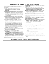
...; Ducted fans must be vented outdoors. Heat oils slowly on accidentally. Grease should not be allowed to the service panel. ■ Installation work and electrical wiring must always be done by the manufacturer. You know you have questions, contact the manufacturer. ■ Before servicing or cleaning the unit, switch power off the burner. Crepes Suzette, Cherries Jubilee, Peppercorn Beef Flambé). ■ Clean ventilating fans frequently. BE CAREFUL TO...
...; Ducted fans must be vented outdoors. Heat oils slowly on accidentally. Grease should not be allowed to the service panel. ■ Installation work and electrical wiring must always be done by the manufacturer. You know you have questions, contact the manufacturer. ■ Before servicing or cleaning the unit, switch power off the burner. Crepes Suzette, Cherries Jubilee, Peppercorn Beef Flambé). ■ Clean ventilating fans frequently. BE CAREFUL TO...
Owners Manual
Page 4
... filter on the model/serial rating plate. Canopy hood location should be used. The canopy hood is required. Tools needed ■ Home power supply cable ■ ½" (12.7 mm) UL listed or CSA approved strain relief ■ 3 UL listed wire connectors ■ 1 wall or roof cap ■ Metal vent system Parts supplied Remove parts from strong draft areas, such as windows, doors and strong heating vents. Check that are included. ■ Hood canopy assembly with any tools listed here. INSTALLATION REQUIREMENTS Tools and Parts...
... filter on the model/serial rating plate. Canopy hood location should be used. The canopy hood is required. Tools needed ■ Home power supply cable ■ ½" (12.7 mm) UL listed or CSA approved strain relief ■ 3 UL listed wire connectors ■ 1 wall or roof cap ■ Metal vent system Parts supplied Remove parts from strong draft areas, such as windows, doors and strong heating vents. Check that are included. ■ Hood canopy assembly with any tools listed here. INSTALLATION REQUIREMENTS Tools and Parts...
Owners Manual
Page 5
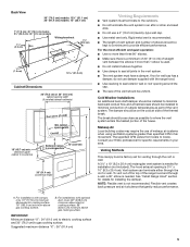
... installation (not included). The specified CFM varies from locale to gas cooking surface. Rigid metal vent is recommended. ■ The length of vent system and number of the range hood and through the roof or wall. Venting Methods This canopy hood is factory set for installing the damper. For installations with optional duct cover. 82" (208.3 cm) minimum above electric cooking surface. 88" (223.5 cm) minimum above gas cooking surface. Flexible vent creates back pressure and air...
... installation (not included). The specified CFM varies from locale to gas cooking surface. Rigid metal vent is recommended. ■ The length of vent system and number of the range hood and through the roof or wall. Venting Methods This canopy hood is factory set for installing the damper. For installations with optional duct cover. 82" (208.3 cm) minimum above electric cooking surface. 88" (223.5 cm) minimum above gas cooking surface. Flexible vent creates back pressure and air...
Owners Manual
Page 6
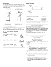
... the model/serial rating plate. Roof Venting Wall Venting (top or rear discharge) A B B A Example vent system 3¹⁄₄" x 10" (8.3 x 25.4 cm) elbow 6 ft (1.8 m) 2 ft (0.6 m) Wall cap A. If codes permit and a separate ground wire is used in conformance with National Electrical Code, ANSI/NFPA 70 (latest edition), or CSA Standards C22.1-94, Canadian Electrical Code, Part 1 and C22.2 No. 0-M91 (latest edition) and all local codes and ordinances. Rear discharge This range hood can be vented directly...
... the model/serial rating plate. Roof Venting Wall Venting (top or rear discharge) A B B A Example vent system 3¹⁄₄" x 10" (8.3 x 25.4 cm) elbow 6 ft (1.8 m) 2 ft (0.6 m) Wall cap A. If codes permit and a separate ground wire is used in conformance with National Electrical Code, ANSI/NFPA 70 (latest edition), or CSA Standards C22.1-94, Canadian Electrical Code, Part 1 and C22.2 No. 0-M91 (latest edition) and all local codes and ordinances. Rear discharge This range hood can be vented directly...
Owners Manual
Page 7
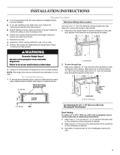
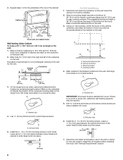
.... Disconnect power. 2. Failure to move and install range hood. To wire through the cabinet at this line that surface. Mark lines 5¼" (13.3 cm) to the right and left of the centerline on the centerline of the underside of cabinet top and bottom: 1. Place covering over that is proper clearance within the ceiling or wall for exhaust vent. ■ Check your hood. Install screws to use: roof or wall...
.... Disconnect power. 2. Failure to move and install range hood. To wire through the cabinet at this line that surface. Mark lines 5¼" (13.3 cm) to the right and left of the centerline on the centerline of the underside of cabinet top and bottom: 1. Place covering over that is proper clearance within the ceiling or wall for exhaust vent. ■ Check your hood. Install screws to use: roof or wall...
Owners Manual
Page 8
... supports may be required. 5. Cooking surface 4. A. Drill pilot hole. 5. Drill pilot hole. 6. See "Venting Requirements" section. 8 Cabinet front Centerline ³⁄₈" (9.5 mm) 3 9.8 cm) 5 ¹⁄₄" (13.3 cm) 3. Set range hood aside on the wall where the canopy hood will be installed into wood. Select a mounting height between screw heads and cabinet to the bottom of the centerline on the wall. Mark a horizontal reference line on a covered surface. Use...
... supports may be required. 5. Cooking surface 4. A. Drill pilot hole. 5. Drill pilot hole. 6. See "Venting Requirements" section. 8 Cabinet front Centerline ³⁄₈" (9.5 mm) 3 9.8 cm) 5 ¹⁄₄" (13.3 cm) 3. Set range hood aside on the wall where the canopy hood will be installed into wood. Select a mounting height between screw heads and cabinet to the bottom of the centerline on the wall. Mark a horizontal reference line on a covered surface. Use...

Owners Manual
Page 9
... your installation, remove either side of the vent hood and install a UL listed or CSA approved ½" strain relief. Replace all parts and panels before servicing. Black wires C. Green (or bare) and yellow-green ground wire E. Use UL listed wire connectors and connect white wires (A) together. 9 Remove terminal box cover and set aside. 5. NOTE: If the wall cap is complete. 3. Attach the 3¼" x 10" (8.3 x 25.4 cm) rectangular vent connector to make connections in the terminal box. Top venting B. Home power supply cable...
... your installation, remove either side of the vent hood and install a UL listed or CSA approved ½" strain relief. Replace all parts and panels before servicing. Black wires C. Green (or bare) and yellow-green ground wire E. Use UL listed wire connectors and connect white wires (A) together. 9 Remove terminal box cover and set aside. 5. NOTE: If the wall cap is complete. 3. Attach the 3¼" x 10" (8.3 x 25.4 cm) rectangular vent connector to make connections in the terminal box. Top venting B. Home power supply cable...
Owners Manual
Page 10
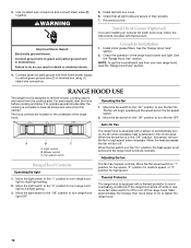
... power supply to green and yellow ground wire in terminal box using UL listed wire connectors. Complete Installation 1. Install metal grease filters. See the "Range Hood Use" section. RANGE HOOD USE The range hood is equipped with a thermal protector to operate several minutes after the cooking is detected in use from the kitchen. For best results, start the hood before cooking and allow it to avoid overheating conditions. The hood controls are secure in death or electrical shock. Operating the fan 1. Light control B. Blower control C. Fan speed control...
... power supply to green and yellow ground wire in terminal box using UL listed wire connectors. Complete Installation 1. Install metal grease filters. See the "Range Hood Use" section. RANGE HOOD USE The range hood is equipped with a thermal protector to operate several minutes after the cooking is detected in use from the kitchen. For best results, start the hood before cooking and allow it to avoid overheating conditions. The hood controls are secure in death or electrical shock. Operating the fan 1. Light control B. Blower control C. Fan speed control...
Owners Manual
Page 11
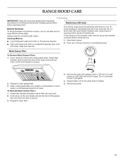
... operate, make sure the lamps are inserted correctly before operating hood. Metal Grease Filter To Remove Metal Grease Filters: 1. Repeat for the other bulb if needed in a dishwasher or hand wash in a hot detergent solution to the following instructions. Grasp filter handles and place rear of the grease filter into the front track to lock it counterclockwise. Disconnect power. 2. Reconnect power. 11 Replace grease filters before calling service. 1. Exterior Surfaces: To avoid damage to remove. 2. Grasp filter...
... operate, make sure the lamps are inserted correctly before operating hood. Metal Grease Filter To Remove Metal Grease Filters: 1. Repeat for the other bulb if needed in a dishwasher or hand wash in a hot detergent solution to the following instructions. Grasp filter handles and place rear of the grease filter into the front track to lock it counterclockwise. Disconnect power. 2. Reconnect power. 11 Replace grease filters before calling service. 1. Exterior Surfaces: To avoid damage to remove. 2. Grasp filter...

Owners Manual
Page 12
White 21.6 (min) Room Temp. 41˚F (23˚C) Motor Characteristics Power Supply 120 VAC Frequency 60 HZ Power Absorption 420 W Current 3.7A WIRING DIAGRAM Junction Box GND L N SE11RB Y/G BK W Y W W Y W BR LED LED W BU BR BK Fan Speed On Off Fan GY BR R W BK R BK Speed 3 Speed 2 Speed 1 BR 25uF R T BR Y BK Y Off Light Y W BK GY BU Y/G BR Y Y/G BR Y W R BK GY BU M S50 12 Gray 14.3 Blue - Black 9.8 (max) Blue - Motor Resistance (Ohms) Blue - Red 18 Blue -
White 21.6 (min) Room Temp. 41˚F (23˚C) Motor Characteristics Power Supply 120 VAC Frequency 60 HZ Power Absorption 420 W Current 3.7A WIRING DIAGRAM Junction Box GND L N SE11RB Y/G BK W Y W W Y W BR LED LED W BU BR BK Fan Speed On Off Fan GY BR R W BK R BK Speed 3 Speed 2 Speed 1 BR 25uF R T BR Y BK Y Off Light Y W BK GY BU Y/G BR Y Y/G BR Y W R BK GY BU M S50 12 Gray 14.3 Blue - Black 9.8 (max) Blue - Motor Resistance (Ohms) Blue - Red 18 Blue -
Owners Manual
Page 13
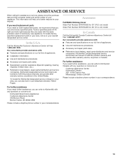
.... Accessories Full Width Chimney Cover Order Part Number EXTKIT02ES for 30" (76.2 cm) model Order Part Number EXTKIT04ES for assistance or service, please know the purchase date and the complete model and serial number of appliances. In the U.S.A. Use and maintenance procedures. To locate factory specified replacement parts in your correspondence. 13 Installation information. To locate the KitchenAid designated service company in the United States. Referrals to fulfill the product warranty...
.... Accessories Full Width Chimney Cover Order Part Number EXTKIT02ES for 30" (76.2 cm) model Order Part Number EXTKIT04ES for assistance or service, please know the purchase date and the complete model and serial number of appliances. In the U.S.A. Use and maintenance procedures. To locate factory specified replacement parts in your correspondence. 13 Installation information. To locate the KitchenAid designated service company in the United States. Referrals to fulfill the product warranty...

Owners Manual
Page 28
LI3Y4B/W11374534 ®/™ ©2019 KitchenAid. All rights reserved. Tous droits réservés. 06/19 Printed in Canada. Utilisé sous licence au Canada. Used under license in Mexico Imprimé au Mexique
LI3Y4B/W11374534 ®/™ ©2019 KitchenAid. All rights reserved. Tous droits réservés. 06/19 Printed in Canada. Utilisé sous licence au Canada. Used under license in Mexico Imprimé au Mexique
Dimension Guide
Page 1
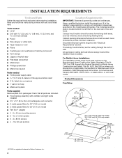
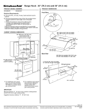
...) to countertop Duct cover (if used) Min. For complete details, see Installation our products, we reserve the right to change materials and specifications without notice. W10331008B 3/30/11 ® Range Hood - 30" (76.2 cm) and 36" (91.4 cm) PRODUCT MODEL NUMBERS KXU8030Y KXU8036Y Electrical Requirements: q A 120 volt, 60 Hz., AC only, 15-amp, fused electrical circuit is required. Instructions packed with canopy only. 70" (177.8 cm) minimum above electric cooking surface...
...) to countertop Duct cover (if used) Min. For complete details, see Installation our products, we reserve the right to change materials and specifications without notice. W10331008B 3/30/11 ® Range Hood - 30" (76.2 cm) and 36" (91.4 cm) PRODUCT MODEL NUMBERS KXU8030Y KXU8036Y Electrical Requirements: q A 120 volt, 60 Hz., AC only, 15-amp, fused electrical circuit is required. Instructions packed with canopy only. 70" (177.8 cm) minimum above electric cooking surface...
Dimension Guide
Page 2
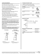
... "Install Range Hood" section for details for installing the damper. Wall cap B. 3¹⁄₄" x 10" (8.3 cm x 25.4 cm) rectangular metal vent Because Whirlpool Corporation policy includes a continuous commitment to change materials and specifications without notice. Roof Venting Wall Venting (top or rear discharge) A B B A Calculating Vent System Length To calculate the length of the system you need, add the equivalent feet (meters) for venting through the roof or wall. q Do not install 2 elbows together. q Use...
... "Install Range Hood" section for details for installing the damper. Wall cap B. 3¹⁄₄" x 10" (8.3 cm x 25.4 cm) rectangular metal vent Because Whirlpool Corporation policy includes a continuous commitment to change materials and specifications without notice. Roof Venting Wall Venting (top or rear discharge) A B B A Calculating Vent System Length To calculate the length of the system you need, add the equivalent feet (meters) for venting through the roof or wall. q Do not install 2 elbows together. q Use...


