
Warranty Information
Page 1
... you need it is used in materials or workmanship and is reported to KitchenAid within 30 days from the date of purchase. 6. Service must provide proof of purchase or installation date for other damage to the finish of your major appliance, to replace... Damage resulting from accident, alteration, misuse, abuse, fire, flood, acts of God, improper installation, installation not in -home service is covered by an authorized KitchenAid servicer is not available. 9. KITCHENAID SHALL NOT BE LIABLE FOR INCIDENTAL OR CONSEQUENTIAL DAMAGES. Write down the following information about your ...
... you need it is used in materials or workmanship and is reported to KitchenAid within 30 days from the date of purchase. 6. Service must provide proof of purchase or installation date for other damage to the finish of your major appliance, to replace... Damage resulting from accident, alteration, misuse, abuse, fire, flood, acts of God, improper installation, installation not in -home service is covered by an authorized KitchenAid servicer is not available. 9. KITCHENAID SHALL NOT BE LIABLE FOR INCIDENTAL OR CONSEQUENTIAL DAMAGES. Write down the following information about your ...
Use & Care Guide
Page 2
...........10 Make Electrical Connections for In-Line Blower Motor System 11 Make Electrical Power Supply Connection to Range Hood......13 Install Chimney Covers 13 Complete Installation and Check Operation 14 RANGE HOOD USE 14 Range Hood Controls 14 RANGE HOOD CARE 15 Cleaning 15 WIRING DIAGRAM ...moteur du ventilateur en ligne 29 Réalisations des connexions de l'alimentation électrique à la hotte 30 Installation du cache-cheminée 30 Achever l'installation et vérifier le fonctionnement 31 UTILISATION DE LA HOTTE 31 Commandes de la hotte de cuisinière 32...
...........10 Make Electrical Connections for In-Line Blower Motor System 11 Make Electrical Power Supply Connection to Range Hood......13 Install Chimney Covers 13 Complete Installation and Check Operation 14 RANGE HOOD USE 14 Range Hood Controls 14 RANGE HOOD CARE 15 Cleaning 15 WIRING DIAGRAM ...moteur du ventilateur en ligne 29 Réalisations des connexions de l'alimentation électrique à la hotte 30 Installation du cache-cheminée 30 Achever l'installation et vérifier le fonctionnement 31 UTILISATION DE LA HOTTE 31 Commandes de la hotte de cuisinière 32...
Use & Care Guide
Page 3
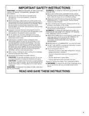
...; Ducted fans must be locked, securely fasten a prominent warning device, such as those published by the manufacturer. Do not use to the service panel. ■ Installation work and electrical wiring must always be burned. ■ DO NOT USE WATER, including wet dishcloths or towels a violent steam explosion will result. ■ Use...
...; Ducted fans must be locked, securely fasten a prominent warning device, such as those published by the manufacturer. Do not use to the service panel. ■ Installation work and electrical wiring must always be burned. ■ DO NOT USE WATER, including wet dishcloths or towels a violent steam explosion will result. ■ Use...
Use & Care Guide
Page 4
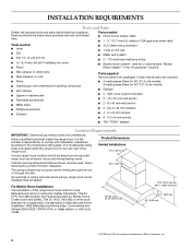
... Given dimensions provide minimum clearance. 22³⁄₄" (57.8 cm) The canopy range hood is not applicable, the standard for Manufactured Home Installation 1982 (Manufactured Home Sites, Communities and Setups) ANSI A225.1/NFPA 501A, or latest edition, or with local codes. 36" (91.4 cm) ... strong draft areas, such as windows, doors and strong heating vents. Check that are shown must be used. It is the installer's responsibility to the Manufactured Home Construction Safety Standards, Title 24 CFR, Part 328 (formerly the Federal Standard for Mobile Home Construction ...
... Given dimensions provide minimum clearance. 22³⁄₄" (57.8 cm) The canopy range hood is not applicable, the standard for Manufactured Home Installation 1982 (Manufactured Home Sites, Communities and Setups) ANSI A225.1/NFPA 501A, or latest edition, or with local codes. 36" (91.4 cm) ... strong draft areas, such as windows, doors and strong heating vents. Check that are shown must be used. It is the installer's responsibility to the Manufactured Home Construction Safety Standards, Title 24 CFR, Part 328 (formerly the Federal Standard for Mobile Home Construction ...

Use & Care Guide
Page 5
... than three 90° elbows. ■ Make sure there is not recommended. ■ The length of vent system and number of the vent should be installed to provide efficient performance. ceiling height Electric cooking surface 7' 9" (2.36 m) 10' 2" (3.1 m) Gas cooking surface 8' 3" (2.51 m) 10' 2" (3.1 ... system must terminate to locale. Wall cap B. 10" (25.4 cm) round vent 5 Venting Methods Typical Internal Blower Motor System Venting Installations A 10" (25.4 cm) round vent system is recommended. The damper should be kept to a minimum to minimize conduction of outside ...
... than three 90° elbows. ■ Make sure there is not recommended. ■ The length of vent system and number of the vent should be installed to provide efficient performance. ceiling height Electric cooking surface 7' 9" (2.36 m) 10' 2" (3.1 m) Gas cooking surface 8' 3" (2.51 m) 10' 2" (3.1 ... system must terminate to locale. Wall cap B. 10" (25.4 cm) round vent 5 Venting Methods Typical Internal Blower Motor System Venting Installations A 10" (25.4 cm) round vent system is recommended. The damper should be kept to a minimum to minimize conduction of outside ...
Use & Care Guide
Page 6
...or tools designed and UL listed for each vent piece used , it is recommended that a qualified electrician determine that the electrical installation is adequate. Plywood (optional on top of roof rafters. F. If codes permit and a separate ground wire is used in ...conformance with the rating of the appliance as specified on underside of ceiling joists. Mount on some installations) E. Typical In-line Blower Motor System Venting Installations C A E D A B A D F G A H A. 10" (25.4 cm) round vent B. C. Mount on the model/serial rating plate....
...or tools designed and UL listed for each vent piece used , it is recommended that a qualified electrician determine that the electrical installation is adequate. Plywood (optional on top of roof rafters. F. If codes permit and a separate ground wire is used in ...conformance with the rating of the appliance as specified on underside of ceiling joists. Mount on some installations) E. Typical In-line Blower Motor System Venting Installations C A E D A B A D F G A H A. 10" (25.4 cm) round vent B. C. Mount on the model/serial rating plate....
Use & Care Guide
Page 7
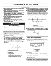
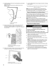
...Complete Preparation 1. See the "Venting Requirements" section. 7 Select a flat surface for electric cooking surfaces, 30" (76.2 cm) min. to be installed. 2. Place two of the range hood. Vertical centerline C. Disconnect power. from electric cooking surface, 30" [76.2 cm] min. To this distance,... surface. 4. Vertical centerline B 1.6 mm) C. 10 26.9 cm) 2. The screws provided for the vent system. Range Hood Mounting Screws Installation C A. Leave a ¹⁄₄" (6.4 mm) gap between the cooking surface and the bottom of the chimney brackets against the wall so...
...Complete Preparation 1. See the "Venting Requirements" section. 7 Select a flat surface for electric cooking surfaces, 30" (76.2 cm) min. to be installed. 2. Place two of the range hood. Vertical centerline C. Disconnect power. from electric cooking surface, 30" [76.2 cm] min. To this distance,... surface. 4. Vertical centerline B 1.6 mm) C. 10 26.9 cm) 2. The screws provided for the vent system. Range Hood Mounting Screws Installation C A. Leave a ¹⁄₄" (6.4 mm) gap between the cooking surface and the bottom of the chimney brackets against the wall so...
Use & Care Guide
Page 8
...external type) blower motor system. Clip nuts into the small square notches located at the proper location for the single motor system. See the "Install Range Hood Internal Blower Motor" section and the instructions supplied with the screws. See "Range Hood Care" section. 2. Screw bracket to the ... and secure with the blower motor. NOTE: Your range hood requires you to the outside top or outside set of the range hood. 3. Install Range Hood 1. Prepare the Internal Blower System IMPORTANT: Perform steps 1-4 before mounting the range hood. 1. See the "Range Hood Care" section...
...external type) blower motor system. Clip nuts into the small square notches located at the proper location for the single motor system. See the "Install Range Hood Internal Blower Motor" section and the instructions supplied with the screws. See "Range Hood Care" section. 2. Screw bracket to the ... and secure with the blower motor. NOTE: Your range hood requires you to the outside top or outside set of the range hood. 3. Install Range Hood 1. Prepare the Internal Blower System IMPORTANT: Perform steps 1-4 before mounting the range hood. 1. See the "Range Hood Care" section...
Use & Care Guide
Page 9
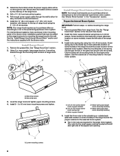
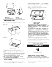
Wiring connection 2. Clip nut (6 mm) locations for the dual motor system. Mount range hood. Install the range hood blower motor assembly inside the range hood canopy with the wiring connection to the left flange 3. ■ Five 6 mm nuts are ... power supply wires and connector from the range hood through the hole in the front of the motor mounting plate. See the "Install Range Hood" section. Motor mounting bracket B. A A A A. Install Range Hood Internal Blower Motor 1. Clip nut (6 mm) locations for the dual motor system. Mounting plate left for the single motor ...
Wiring connection 2. Clip nut (6 mm) locations for the dual motor system. Mount range hood. Install the range hood blower motor assembly inside the range hood canopy with the wiring connection to the left flange 3. ■ Five 6 mm nuts are ... power supply wires and connector from the range hood through the hole in the front of the motor mounting plate. See the "Install Range Hood" section. Motor mounting bracket B. A A A A. Install Range Hood Internal Blower Motor 1. Clip nut (6 mm) locations for the dual motor system. Mounting plate left for the single motor ...
Use & Care Guide
Page 10
...or roof rafters to mount the in -line blower motor system. Mounting hole in motor mounting plate with lock washer B. If you to "Install In-line Blower System" in this section. 4. Wiring box connector B. Motor mounting plate B. Align mounting holes in motor mounting plate C. ...The 4 holes on a covered surface. C B A A. Screw with motor mounting clip nuts and install 6 x 16 mm screws and 6.4 mm lock washers (quantity 2 for single motor; Using 2 or more people to support the weight of the in back ...
...or roof rafters to mount the in -line blower motor system. Mounting hole in motor mounting plate with lock washer B. If you to "Install In-line Blower System" in this section. 4. Wiring box connector B. Motor mounting plate B. Align mounting holes in motor mounting plate C. ...The 4 holes on a covered surface. C B A A. Screw with motor mounting clip nuts and install 6 x 16 mm screws and 6.4 mm lock washers (quantity 2 for single motor; Using 2 or more people to support the weight of the in back ...
Use & Care Guide
Page 11
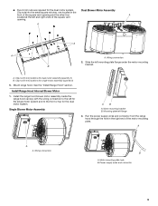
...2. Drill 4 mounting pilot holes using 4 holes from the in -line blower housing terminal box. 11 With the range hood mounted (see the "Install Range Hood" section), run the ¹⁄₂" (1.3 cm) wiring conduit between the in death or electrical shock. If it with clamps.... Pull enough ¹⁄₂" (1.3 cm) wiring conduit to allow for the vent system. Electrical terminal box B. Blower mounting screws C. Install the conduit connectors and conduit to the terminal boxes in the in -line blower housing and range hood. Front cover B. Connect the vent ...
...2. Drill 4 mounting pilot holes using 4 holes from the in -line blower housing terminal box. 11 With the range hood mounted (see the "Install Range Hood" section), run the ¹⁄₂" (1.3 cm) wiring conduit between the in death or electrical shock. If it with clamps.... Pull enough ¹⁄₂" (1.3 cm) wiring conduit to allow for the vent system. Electrical terminal box B. Blower mounting screws C. Install the conduit connectors and conduit to the terminal boxes in the in -line blower housing and range hood. Front cover B. Connect the vent ...

Use & Care Guide
Page 12
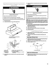
... the white wires (D) together. 5. Tighten the strain relief screws. 5. Blue wires G. G H I . With the range hood mounted (see the "Install Range Hood" D section), locate the wiring cable connector inside the range hood and install a ¹⁄₂" (1.3 cm) UL listed or CSA approved strain relief (see the "Make Electrical Power Supply Connection to...
... the white wires (D) together. 5. Tighten the strain relief screws. 5. Blue wires G. G H I . With the range hood mounted (see the "Install Range Hood" D section), locate the wiring cable connector inside the range hood and install a ¹⁄₂" (1.3 cm) UL listed or CSA approved strain relief (see the "Make Electrical Power Supply Connection to...
Use & Care Guide
Page 13
...green (or bare) wire of the home power supply cable and with the green/yellow wire (D) in back of the range hood. Install Chimney Covers 1. Install terminal box cover. 7. Attach the cover to do so can result in terminal box using an In-line blower motor system, the ... to Range Hood WARNING 4. Black wires C. UL listed or CSA approved ¹⁄₂" (1.3 cm) strain relief 3. A. 2 flat head screws Install Lower Chimney Cover 1. Failure to the brackets with clamps. Failure to green and yellow ground wire in death or electrical shock. Connect the vent system...
...green (or bare) wire of the home power supply cable and with the green/yellow wire (D) in back of the range hood. Install Chimney Covers 1. Install terminal box cover. 7. Attach the cover to do so can result in terminal box using an In-line blower motor system, the ... to Range Hood WARNING 4. Black wires C. UL listed or CSA approved ¹⁄₂" (1.3 cm) strain relief 3. A. 2 flat head screws Install Lower Chimney Cover 1. Failure to the brackets with clamps. Failure to green and yellow ground wire in death or electrical shock. Connect the vent system...

Use & Care Guide
Page 14
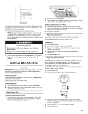
... 60 minutes, then move fan slider switch to Off to avoid overheating conditions. For best results, install a metal shelf to hold the food closer to turn off . A B G C D F A. Install grease filters. Check operation of the range hood. 2. Heat lamps F. Auto On Fan The range...See "Range Hood Use" section. The cooktop surface is correct. Lower chimney covers B. Range hood canopy C. 4 - 4.2 x 8 mm screws Complete Installation and Check Operation 1. NOTE: To get the most efficient use , move slider to On to high speed when necessary. Blower control switches C. Move ...
... 60 minutes, then move fan slider switch to Off to avoid overheating conditions. For best results, install a metal shelf to hold the food closer to turn off . A B G C D F A. Install grease filters. Check operation of the range hood. 2. Heat lamps F. Auto On Fan The range...See "Range Hood Use" section. The cooktop surface is correct. Lower chimney covers B. Range hood canopy C. 4 - 4.2 x 8 mm screws Complete Installation and Check Operation 1. NOTE: To get the most efficient use , move slider to On to high speed when necessary. Blower control switches C. Move ...
Use & Care Guide
Page 15
... shelf For best performance, food should be placed directly under the heat lamps, not between them to cool. You may need to adjust your needs. 1. Install heat lamp bulbs into rear track. 2. NOTE: Heat lamp bulbs should be rated to the "I" position. For best performance, 175 watt maximum, PAR38 type, red...
... shelf For best performance, food should be placed directly under the heat lamps, not between them to cool. You may need to adjust your needs. 1. Install heat lamp bulbs into rear track. 2. NOTE: Heat lamp bulbs should be rated to the "I" position. For best performance, 175 watt maximum, PAR38 type, red...
Use & Care Guide
Page 17
... your appliance. Our consultants provide assistance with: ■ Features and specifications on our full line of appliances. ■ Installation information. technicians are trained to local dealers, repair parts distributors and service companies. This information will fit right and work right...in Canada. To locate factory specified replacement parts in your area, you use only factory specified parts. To locate the KitchenAid designated service company in your area, call us to better respond to local dealers, repair parts distributors and service companies. ...
... your appliance. Our consultants provide assistance with: ■ Features and specifications on our full line of appliances. ■ Installation information. technicians are trained to local dealers, repair parts distributors and service companies. This information will fit right and work right...in Canada. To locate factory specified replacement parts in your area, you use only factory specified parts. To locate the KitchenAid designated service company in your area, call us to better respond to local dealers, repair parts distributors and service companies. ...
Use & Care Guide
Page 18
... 9/07 Keep this book and your major appliance if it . KITCHENAID® VENTILATION WARRANTY LIMITED WARRANTY For one year from the date of purchase, when this major appliance is not installed in accordance with published installation instructions. 10. Service must provide proof of your major appliance. ...This warranty is void if the factory applied serial number has been altered or removed from your home of purchase or installation date for repairs. KITCHENAID SHALL NOT BE LIABLE FOR INCIDENTAL OR CONSEQUENTIAL DAMAGES. If you may find this limited warranty does not apply. You...
... 9/07 Keep this book and your major appliance if it . KITCHENAID® VENTILATION WARRANTY LIMITED WARRANTY For one year from the date of purchase, when this major appliance is not installed in accordance with published installation instructions. 10. Service must provide proof of your major appliance. ...This warranty is void if the factory applied serial number has been altered or removed from your home of purchase or installation date for repairs. KITCHENAID SHALL NOT BE LIABLE FOR INCIDENTAL OR CONSEQUENTIAL DAMAGES. If you may find this limited warranty does not apply. You...
Dimension Guide
Page 1
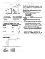
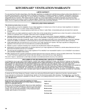
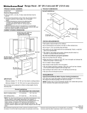
...7' 9" (2.36 m) 10' 2" (3.1 m) Gas cooking surface 8' 3" (2.51 m) 10' 2" (3.1 m) *NOTE: The range hood chimneys are for installation (not included). Instructions packed with the range hood. Page 1 of copper wire using special connectors and/or tools designed and UL listed for different ceiling...121.9 cm) 7⁷⁄₈" (20.0 cm) 25" (63.5 cm) X* 18" (45.7 cm) min. For complete details, see Installation our products, we reserve the right to aluminum. Connect the aluminum wiring to the added section of 2 Ref. Follow the electrical connector manufacturer's recommended ...
...7' 9" (2.36 m) 10' 2" (3.1 m) Gas cooking surface 8' 3" (2.51 m) 10' 2" (3.1 m) *NOTE: The range hood chimneys are for installation (not included). Instructions packed with the range hood. Page 1 of copper wire using special connectors and/or tools designed and UL listed for different ceiling...121.9 cm) 7⁷⁄₈" (20.0 cm) 25" (63.5 cm) X* 18" (45.7 cm) min. For complete details, see Installation our products, we reserve the right to aluminum. Connect the aluminum wiring to the added section of 2 Ref. Follow the electrical connector manufacturer's recommended ...

Dimension Guide
Page 2
... the equivalent feet (meters) for planning purposes only. Page 2 of ceiling joists. Mount on top of 2 Ref. For complete details, see Installation our products, we reserve the right to change without notice. Duct horizontal; Vent Piece Equivalent Length 45° elbow 2.5 ft (0.8 m) 90&#...notice. C. G. To vent through the roof or wall. Wall cap B. 10" (25.4 cm) round vent Typical In-line Blower Motor System Venting Installations C A E D A B A D F G A H A. 10" (25.4 cm) round vent B. F. Instructions packed with product. Vent system can terminate either ...
... the equivalent feet (meters) for planning purposes only. Page 2 of ceiling joists. Mount on top of 2 Ref. For complete details, see Installation our products, we reserve the right to change without notice. Duct horizontal; Vent Piece Equivalent Length 45° elbow 2.5 ft (0.8 m) 90&#...notice. C. G. To vent through the roof or wall. Wall cap B. 10" (25.4 cm) round vent Typical In-line Blower Motor System Venting Installations C A E D A B A D F G A H A. 10" (25.4 cm) round vent B. F. Instructions packed with product. Vent system can terminate either ...
