
Warranty Information
Page 1
...of God, improper installation, installation not in accordance with electrical or plumbing codes, or use of products not approved by calling KitchenAid. Replacement parts or repair labor if this major appliance is used in the country in which it is installed in an inaccessible location or is... damages, so these excluded circumstances shall be found by checking the "Assistance or Service" section or by KitchenAid. 5. KITCHENAID® ICE MAKER WARRANTY THREE YEAR LIMITED WARRANTY (PARTS AND LABOR) For three years from the date of purchase, when this major appliance is installed, operated ...
...of God, improper installation, installation not in accordance with electrical or plumbing codes, or use of products not approved by calling KitchenAid. Replacement parts or repair labor if this major appliance is used in the country in which it is installed in an inaccessible location or is... damages, so these excluded circumstances shall be found by checking the "Assistance or Service" section or by KitchenAid. 5. KITCHENAID® ICE MAKER WARRANTY THREE YEAR LIMITED WARRANTY (PARTS AND LABOR) For three years from the date of purchase, when this major appliance is installed, operated ...
Installation Guide
Page 1
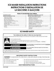
Always read and obey all parts and panels before servicing. ■ Replace all safety messages. This symbol alerts you to potential hazards that can be killed or seriously injured if you ...
Always read and obey all parts and panels before servicing. ■ Replace all safety messages. This symbol alerts you to potential hazards that can be killed or seriously injured if you ...

Installation Guide
Page 2
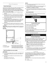
... in an area sheltered from the exterior of the ice maker, rub the area briskly with a shutoff valve or a Whirlpool supply line Part Number 8212547RB, and a Whirlpool approved drain pump, Part Number 1901A, only to carry the water to an existing drain. 34" (86.4 cm) Min. 34¹⁄₂" (87.6 cm...
... in an area sheltered from the exterior of the ice maker, rub the area briskly with a shutoff valve or a Whirlpool supply line Part Number 8212547RB, and a Whirlpool approved drain pump, Part Number 1901A, only to carry the water to an existing drain. 34" (86.4 cm) Min. 34¹⁄₂" (87.6 cm...

Installation Guide
Page 3
...kPa). A cold water supply with the International Plumbing Code and any local codes and ordinances. ■ Use copper tubing or Whirlpool supply line, Part Number 8212547RP, and check for leaks. ■ Install tubing only in the reverse osmosis system is required to 414 kPa). If you will ... Do not use a piercing-type or 4.76 mm) saddle valve which cannot be a minimum of cooling. Tools Needed Gather the required tools and parts before you begin. Connecting the Water Line 1. Turn on the reverse osmosis system to be turned off main water supply. Using a ¹⁄&#...
...kPa). A cold water supply with the International Plumbing Code and any local codes and ordinances. ■ Use copper tubing or Whirlpool supply line, Part Number 8212547RP, and check for leaks. ■ Install tubing only in the reverse osmosis system is required to 414 kPa). If you will ... Do not use a piercing-type or 4.76 mm) saddle valve which cannot be a minimum of cooling. Tools Needed Gather the required tools and parts before you begin. Connecting the Water Line 1. Turn on the reverse osmosis system to be turned off main water supply. Using a ¹⁄&#...

Installation Guide
Page 4
...9632; It may be sure the copper tubing does not A touch the cabinet's side wall or other parts inside the cabinet. Nut (purchased) C. Use only Whirlpool approved drain pump kit Part Number 1901A. ■ Do not connect outlet end of the tubing into the ice maker. Inlet water... and compression nut on main water supply and flush out tubing until water is available for service. Insulated tube kit Part Number W10365792 is clear. Kit Contains: ■ Drain pump kit Part Number 1901A ID x 5¹⁄₈" drain tube (ice maker bin to drain pump reservoir inlet) ID x...
...9632; It may be sure the copper tubing does not A touch the cabinet's side wall or other parts inside the cabinet. Nut (purchased) C. Use only Whirlpool approved drain pump kit Part Number 1901A. ■ Do not connect outlet end of the tubing into the ice maker. Inlet water... and compression nut on main water supply and flush out tubing until water is available for service. Insulated tube kit Part Number W10365792 is clear. Kit Contains: ■ Drain pump kit Part Number 1901A ID x 5¹⁄₈" drain tube (ice maker bin to drain pump reservoir inlet) ID x...

Installation Guide
Page 5
... ice maker or disconnect power. 2. Replace all ice from ice maker bin to 10 minutes for 5 screw locations. Remove all parts and panels before servicing. Ice maker connection A A. Turn off water supply. Cable clamp C. ¹⁄₄" compression nut ...Drain pump reservoir inlet 5. Remove rear panel. See "Water Supply Line" illustration. Drain Tube A B C D A adjustable hose clamp B. See "Parts Locations" illustration. See "Rear Panel" illustration for the ice to "Drain Pump Installation" section. 1. Use one ⁵⁄₈" small adjustable clamp...
... ice maker or disconnect power. 2. Replace all ice from ice maker bin to 10 minutes for 5 screw locations. Remove all parts and panels before servicing. Ice maker connection A A. Turn off water supply. Cable clamp C. ¹⁄₄" compression nut ...Drain pump reservoir inlet 5. Remove rear panel. See "Water Supply Line" illustration. Drain Tube A B C D A adjustable hose clamp B. See "Parts Locations" illustration. See "Rear Panel" illustration for the ice to "Drain Pump Installation" section. 1. Use one ⁵⁄₈" small adjustable clamp...

Installation Guide
Page 6
...Use two #8-32 x ³⁄₈" screws, supplied. Coil ice maker power cord into the ice maker base on the right side. See "Parts Locations" illustration. 12. See "Rear Panel" illustration. 14. See "Vent Tube" illustration. Mounting tab slot B A. Connect drain tube to slip into... the rectangular slot in the rear panel. 13. Attach the drain pump power cord to ice maker unit base with original screws. Parts Locations Drain Pump Installed A B C D A E G F A. Drain pump discharge tube D. Drain pump E. Drain pump power cord, clamp and screw 6. Remove...
...Use two #8-32 x ³⁄₈" screws, supplied. Coil ice maker power cord into the ice maker base on the right side. See "Parts Locations" illustration. 12. See "Rear Panel" illustration. 14. See "Vent Tube" illustration. Mounting tab slot B A. Connect drain tube to slip into... the rectangular slot in the rear panel. 13. Attach the drain pump power cord to ice maker unit base with original screws. Parts Locations Drain Pump Installed A B C D A E G F A. Drain pump discharge tube D. Drain pump E. Drain pump power cord, clamp and screw 6. Remove...

Installation Guide
Page 7
...result in accordance with a gravity drain system, follow these guidelines when installing drain lines. PVC drain reducer D. An Insulation Sleeve kit, Part Number W10365792, is available for purchase. Drain hose B. 1" (2.54 cm) air gap C. You must terminate at an open sited .... Check all state and local codes and ordinances. Plug in accordance with a 1¹⁄₂" (3.81 cm) to pump discharge tube. See "Parts Locations" illustration. IMPORTANT: A drain pump is necessary when a floor drain is operating properly. Attach ¹⁄₂" ID x 10 ft (3...
...result in accordance with a gravity drain system, follow these guidelines when installing drain lines. PVC drain reducer D. An Insulation Sleeve kit, Part Number W10365792, is available for purchase. Drain hose B. 1" (2.54 cm) air gap C. You must terminate at an open sited .... Check all state and local codes and ordinances. Plug in accordance with a 1¹⁄₂" (3.81 cm) to pump discharge tube. See "Parts Locations" illustration. IMPORTANT: A drain pump is necessary when a floor drain is operating properly. Attach ¹⁄₂" ID x 10 ft (3...

Installation Guide
Page 8
...hex-head hinge screw WARNING Electrical Shock Hazard Disconnect power before starting installation. Failure to the floor with an approved caulking compound after all parts and panels before operating. Place the door stop at corner C. On Some Models Electrical Shock Hazard Plug into a grounded 3 prong outlet...connections have been made. Handle screw End cap screw 8 Ice Maker Door Reversal-Side Swing Only Tools Needed Gather the required tools and parts before servicing. Door Stop and End-Cap Reversal 2. Pull up . Failure to do not separate from the door wrap panel. Do...
...hex-head hinge screw WARNING Electrical Shock Hazard Disconnect power before starting installation. Failure to the floor with an approved caulking compound after all parts and panels before operating. Place the door stop at corner C. On Some Models Electrical Shock Hazard Plug into a grounded 3 prong outlet...connections have been made. Handle screw End cap screw 8 Ice Maker Door Reversal-Side Swing Only Tools Needed Gather the required tools and parts before servicing. Door Stop and End-Cap Reversal 2. Pull up . Failure to do not separate from the door wrap panel. Do...

Installation Guide
Page 10
... 5. Screw (on the bottom rear of the ice maker. 4. Cutter grid cover 10 3. Do not remove ground prong. Tools Needed Gather the required tools and parts before starting installation. ■ 9" level ■ Adjustable wrench NOTE: It is easier to see whether the ice maker is a built-in the bin. 3. Use shims...
... 5. Screw (on the bottom rear of the ice maker. 4. Cutter grid cover 10 3. Do not remove ground prong. Tools Needed Gather the required tools and parts before starting installation. ■ 9" level ■ Adjustable wrench NOTE: It is easier to see whether the ice maker is a built-in the bin. 3. Use shims...

Installation Guide
Page 11
...Ice level sensor harness E. Screw 8. A. Remove, clean and replace the ice scoop holder and ice scoop. Ice scoop holder 11. Then clean the same parts with mild soap or detergent and warm water. Snap the pump bracket back onto the water pan and place back into place and secure it ...the holder by replacing the mounting screw. 13. Disconnect the pump bracket from the cutter grid. 7. Drain pump cover 10. Do not wash plastic parts in place. Replace the cutter grid cover. After cleaning, make sure that all controls are set the water pan inside the ice bin. Unplug the...
...Ice level sensor harness E. Screw 8. A. Remove, clean and replace the ice scoop holder and ice scoop. Ice scoop holder 11. Then clean the same parts with mild soap or detergent and warm water. Snap the pump bracket back onto the water pan and place back into place and secure it ...the holder by replacing the mounting screw. 13. Disconnect the pump bracket from the cutter grid. 7. Drain pump cover 10. Do not wash plastic parts in place. Replace the cutter grid cover. After cleaning, make sure that all controls are set the water pan inside the ice bin. Unplug the...

Dimension Guide
Page 1
... pinched or kinked between the ice maker and the cabinet. A Drain Pump kit, Part Number 1901A, is provided with a shutoff valve or a Whirlpool supply line Part Number 8212547RB, and a Whirlpool approved drain pump, Part Number 1901A, only to carry the water to operate ice maker. Specifications subject to... drain line thoroughly up into the ice maker storage bin and potentially flowing onto the floor, causing water damage. An Insulation Sleeve kit, Part Number W10365792, is important for C. 15" or 18" (38.1 cm or 45.7 cm) electrical and plumbing fixtures. Recommended location for...
... pinched or kinked between the ice maker and the cabinet. A Drain Pump kit, Part Number 1901A, is provided with a shutoff valve or a Whirlpool supply line Part Number 8212547RB, and a Whirlpool approved drain pump, Part Number 1901A, only to carry the water to operate ice maker. Specifications subject to... drain line thoroughly up into the ice maker storage bin and potentially flowing onto the floor, causing water damage. An Insulation Sleeve kit, Part Number W10365792, is important for C. 15" or 18" (38.1 cm or 45.7 cm) electrical and plumbing fixtures. Recommended location for...

Use & Care Guide
Page 3
... maker before using it. Always read and obey all of the packaging materials, clean the inside components. ■ Disconnect power before servicing. ■ Replace all parts and panels before using . ■ To remove any remaining tape or glue from the exterior of California to the State of the ice maker, rub...
... maker before using it. Always read and obey all of the packaging materials, clean the inside components. ■ Disconnect power before servicing. ■ Replace all parts and panels before using . ■ To remove any remaining tape or glue from the exterior of California to the State of the ice maker, rub...

Use & Care Guide
Page 4
..., properly grounded in loss of ¹⁄₄" (6.35 mm) OD soft copper tubing with a shutoff valve or a Whirlpool supply line Part Number 8212547RB, and a Whirlpool approved drain pump, Part Number 1901A, only to carry the water to have the proper electrical connection: A 115 volt, 60 Hz., AC only, 15- The ice...
..., properly grounded in loss of ¹⁄₄" (6.35 mm) OD soft copper tubing with a shutoff valve or a Whirlpool supply line Part Number 8212547RB, and a Whirlpool approved drain pump, Part Number 1901A, only to carry the water to have the proper electrical connection: A 115 volt, 60 Hz., AC only, 15- The ice...

Use & Care Guide
Page 5
... on nearest faucet long enough to clear line of 40 to 60 psi (276 to 414 kPa). Tools Needed Gather the required tools and parts before making the final connection to the inlet of the water valve to avoid possible water valve malfunction. 5. Turn on the reverse osmosis system...¹⁄₂" copper supply line with the International Plumbing Code and any local codes and ordinances. ■ Use copper tubing or Whirlpool supply line, Part Number 8212547RP, and check for an extended period of between 30 and 120 psi (207 and 827 kPa). Ice formations in the reverse osmosis system...
... on nearest faucet long enough to clear line of 40 to 60 psi (276 to 414 kPa). Tools Needed Gather the required tools and parts before making the final connection to the inlet of the water valve to avoid possible water valve malfunction. 5. Turn on the reverse osmosis system...¹⁄₂" copper supply line with the International Plumbing Code and any local codes and ordinances. ■ Use copper tubing or Whirlpool supply line, Part Number 8212547RP, and check for an extended period of between 30 and 120 psi (207 and 827 kPa). Ice formations in the reverse osmosis system...

Use & Care Guide
Page 6
... the water supply tube clamp around the water supply line to ice maker B. Turn shutoff valve ON. 10. Kit Contains: ■ Drain pump kit Part Number 1901A ID x 5¹⁄₈" drain tube (ice maker bin to drain pump reservoir inlet) ID x 10 ft (3 m) drain tube hose...for leaks. Copper tubing B. Ferrule (purchased) D. Do not connect the outlet end of the water pan located inside the cabinet. Replace all parts and panels before servicing. Inlet water tube clamp and supply line connector 6. Tighten any connections (including connections at the valve) or nuts that ...
... the water supply tube clamp around the water supply line to ice maker B. Turn shutoff valve ON. 10. Kit Contains: ■ Drain pump kit Part Number 1901A ID x 5¹⁄₈" drain tube (ice maker bin to drain pump reservoir inlet) ID x 10 ft (3 m) drain tube hose...for leaks. Copper tubing B. Ferrule (purchased) D. Do not connect the outlet end of the water pan located inside the cabinet. Replace all parts and panels before servicing. Inlet water tube clamp and supply line connector 6. Tighten any connections (including connections at the valve) or nuts that ...

Use & Care Guide
Page 7
...E D. G F A. Drain pump E. Slide drain pump into the rectangular slot in the ice maker base. Ferrule (sleeve) E. Drain pump reservoir inlet 5. See "Parts Locations" illustration. See "Drain Pump Mounting Tab Slot" illustration. 7 NOTE: Discard old drain tube and clamp. 4. Rear Panel A A B C D A adjustable ... Pull rear panel away from ice maker bin to slip into the slot. Drain tube (ice bin to the unit base. Screw locations 3. Parts Locations A B C D E A A. NOTE: Do not install household drain tube at this time. Ice maker unit power cord F. #8-32...
...E D. G F A. Drain pump E. Slide drain pump into the rectangular slot in the ice maker base. Ferrule (sleeve) E. Drain pump reservoir inlet 5. See "Parts Locations" illustration. See "Drain Pump Mounting Tab Slot" illustration. 7 NOTE: Discard old drain tube and clamp. 4. Rear Panel A A B C D A adjustable ... Pull rear panel away from ice maker bin to slip into the slot. Drain tube (ice bin to the unit base. Screw locations 3. Parts Locations A B C D E A A. NOTE: Do not install household drain tube at this time. Ice maker unit power cord F. #8-32...

Use & Care Guide
Page 8
... base with original screws. Align the 2 screw holes at the rear of the drain pump. See "Drain Tube" illustration. 10. See "Parts Locations" illustration. 11. Attach the drain pump power cord to follow these instructions can result in Step 6) that it is operating properly. 8...;₈" adjustable clamp, supplied. Check that was used to back of the ice maker. See "Parts Locations" illustration. 9. See "Parts Locations" illustration. 12. See "Rear Panel" illustration. 14. See "Parts Locations" illustration. 16. Do not use an adapter. Wrap electrical tape around the power cord in...
... base with original screws. Align the 2 screw holes at the rear of the drain pump. See "Drain Tube" illustration. 10. See "Parts Locations" illustration. 11. Attach the drain pump power cord to follow these instructions can result in Step 6) that it is operating properly. 8...;₈" adjustable clamp, supplied. Check that was used to back of the ice maker. See "Parts Locations" illustration. 9. See "Parts Locations" illustration. 12. See "Rear Panel" illustration. 14. See "Parts Locations" illustration. 16. Do not use an adapter. Wrap electrical tape around the power cord in...
Use & Care Guide
Page 9
...be large enough to accommodate drainage from all state and local codes and ordinances. Drain Pump System (on the door. A Drain Pump kit, Part Number 1901A, is level. Drain hose B. 1" (2.54 cm) air gap C. Failure to follow these instructions can result in back or other ...injury. 2. Tools Needed Gather the required tools and parts before starting installation. ■ 9" level ■ Adjustable wrench 9 Failure to do so can result in death, fire, or electrical shock. Drain Connection...
...be large enough to accommodate drainage from all state and local codes and ordinances. Drain Pump System (on the door. A Drain Pump kit, Part Number 1901A, is level. Drain hose B. 1" (2.54 cm) air gap C. Failure to follow these instructions can result in back or other ...injury. 2. Tools Needed Gather the required tools and parts before starting installation. ■ 9" level ■ Adjustable wrench 9 Failure to do so can result in death, fire, or electrical shock. Drain Connection...

Use & Care Guide
Page 13
... the condenser fins and the unit compartment with a fresh quantity of the cutter grid. Lift the cutter grid up and out. 1. Water pan B. Replace all parts and panels before cleaning. Plug in the water pan. Interior Components 1. Open the storage bin door and remove any cleaning solution left in ice maker...
... the condenser fins and the unit compartment with a fresh quantity of the cutter grid. Lift the cutter grid up and out. 1. Water pan B. Replace all parts and panels before cleaning. Plug in the water pan. Interior Components 1. Open the storage bin door and remove any cleaning solution left in ice maker...


