Use and Care Guide
Page 30
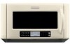
... on during microwave oven operation to cool the microwave oven's controls while the cooktop below . Fan running during microwave oven operation. 30 See Installation Instructions provided with your microwave oven. See "Assistance or Service" section. ■ Is the door completely closed for...properly. The fan will not affect performance. Make sure these items during cooktop usage ■ This is sitting securely on some models) attached to normal room temperature. See "Timer" section. ■ Is the Learning Mode in the home. See "Microwave Cooking Power" section....
... on during microwave oven operation to cool the microwave oven's controls while the cooktop below . Fan running during microwave oven operation. 30 See Installation Instructions provided with your microwave oven. See "Assistance or Service" section. ■ Is the door completely closed for...properly. The fan will not affect performance. Make sure these items during cooktop usage ■ This is sitting securely on some models) attached to normal room temperature. See "Timer" section. ■ Is the Learning Mode in the home. See "Microwave Cooking Power" section....

Use and Care Guide
Page 32
...through fifth years from the date of purchase, when this appliance is operated and maintained according to instructions attached to or furnished with the product, KitchenAid or KitchenAid Canada will pay for factory specified parts for the following information about your appliance if it . Those... from the date of purchase, when this major appliance is operated and maintained according to instructions attached to or furnished with the product, KitchenAid or KitchenAid Canada (hereafter "KitchenAid") will pay for factory specified parts for the stainless steel oven cavity/inner door if the ...
...through fifth years from the date of purchase, when this appliance is operated and maintained according to instructions attached to or furnished with the product, KitchenAid or KitchenAid Canada will pay for factory specified parts for the following information about your appliance if it . Those... from the date of purchase, when this major appliance is operated and maintained according to instructions attached to or furnished with the product, KitchenAid or KitchenAid Canada (hereafter "KitchenAid") will pay for factory specified parts for the stainless steel oven cavity/inner door if the ...
Installation Instructions
Page 1
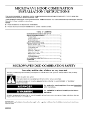
...Dimensions 3 Electrical Requirements 3 INSTALLATION INSTRUCTIONS 4 Remove Mounting Plate 4 Convert Oven to External Venting 4 Locate Wall Stud(s 6 Mark Rear Wall 7 Drill Holes in Rear Wall 7 Attach Mounting Plate to Wall 8 Prepare Upper Cabinet 8 Install the Oven 9 Complete Installation 10 VENTING DESIGN SPECIFICATIONS 11 ASSISTANCE 12 Replacement Parts 12 MICROWAVE HOOD COMBINATION... Instructions for further notes. See "Installation Requirements" section for local house inspector's use above electric or gas cooking products up to and including 30" (76.2 cm) wide.
...Dimensions 3 Electrical Requirements 3 INSTALLATION INSTRUCTIONS 4 Remove Mounting Plate 4 Convert Oven to External Venting 4 Locate Wall Stud(s 6 Mark Rear Wall 7 Drill Holes in Rear Wall 7 Attach Mounting Plate to Wall 8 Prepare Upper Cabinet 8 Install the Oven 9 Complete Installation 10 VENTING DESIGN SPECIFICATIONS 11 ASSISTANCE 12 Replacement Parts 12 MICROWAVE HOOD COMBINATION... Instructions for further notes. See "Installation Requirements" section for local house inspector's use above electric or gas cooking products up to and including 30" (76.2 cm) wide.
Installation Instructions
Page 2
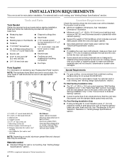
.... Toggle nuts (4) E. 1/4" x 2" lag screws (4) F. Vent deflector (for wall or roof venting) Not Shown: Upper cabinet template Mounting plate (attached to make sure there is at least 3" (7.6 cm) of 150 lbs (68 kg), which includes oven and items placed inside the oven and upper cabinet...exceed 50,000 BTU/hr. ■ The oven is set for recirculation installation. For Wall Venting Installation Only: ■ The 12" x 4" (30.5 x 10.2 cm) cutout area (see "Venting Design Specifications" section. Tools and Parts Tools Needed Gather the required tools and parts before starting ...
.... Toggle nuts (4) E. 1/4" x 2" lag screws (4) F. Vent deflector (for wall or roof venting) Not Shown: Upper cabinet template Mounting plate (attached to make sure there is at least 3" (7.6 cm) of 150 lbs (68 kg), which includes oven and items placed inside the oven and upper cabinet...exceed 50,000 BTU/hr. ■ The oven is set for recirculation installation. For Wall Venting Installation Only: ■ The 12" x 4" (30.5 x 10.2 cm) cutout area (see "Venting Design Specifications" section. Tools and Parts Tools Needed Gather the required tools and parts before starting ...

Installation Instructions
Page 4
... may be used. To prepare the oven for recirculation installation. Back of oven B. Top of oven C. Vent screen C. Tape the oven door closed so that attach it back and under the back edge of the oven, and set for wall or roof venting, the vent deflector (Lshaped metal bar) must be...
... may be used. To prepare the oven for recirculation installation. Back of oven B. Top of oven C. Vent screen C. Tape the oven door closed so that attach it back and under the back edge of the oven, and set for wall or roof venting, the vent deflector (Lshaped metal bar) must be...

Installation Instructions
Page 7
...the centerline, and mark. 8. This is level with toggle nuts; Following are ideal hole locations. 5. Refer to complete the 12" x 4" (30.5 x 10.2 cm) rectangle. Holding the mounting plate in "Locate Wall Stud(s)" section. Using measuring tape, measure out 6" (15.2 cm) on...3/16" (5 mm) holes into the wall stud(s) at the 4 corner holes marked in "Locate Wall Stud(s)" section. Top of mounting plate must attach to figures 1 and 2 in "Possible Wall Stud Configurations" in Step 3 of "Mark Rear Wall." A Wall Venting Installation Only Centerline Upper cabinet bottom...
...the centerline, and mark. 8. This is level with toggle nuts; Following are ideal hole locations. 5. Refer to complete the 12" x 4" (30.5 x 10.2 cm) rectangle. Holding the mounting plate in "Locate Wall Stud(s)" section. Using measuring tape, measure out 6" (15.2 cm) on...3/16" (5 mm) holes into the wall stud(s) at the 4 corner holes marked in "Locate Wall Stud(s)" section. Top of mounting plate must attach to figures 1 and 2 in "Possible Wall Stud Configurations" in Step 3 of "Mark Rear Wall." A Wall Venting Installation Only Centerline Upper cabinet bottom...

Installation Instructions
Page 8
... from the back of the upper cabinet. 4. Spring toggle nut 5. Upper-cabinet template D E 10¹⁄₂" 10¹⁄₂" (26.7 cm) F (26.7 cm) G 8 Attach Mounting Plate to Wall NOTE: Secure the mounting plate to the wall at all lag screws. Start toggle nuts on a second wall stud, insert lag...
... from the back of the upper cabinet. 4. Spring toggle nut 5. Upper-cabinet template D E 10¹⁄₂" 10¹⁄₂" (26.7 cm) F (26.7 cm) G 8 Attach Mounting Plate to Wall NOTE: Secure the mounting plate to the wall at all lag screws. Start toggle nuts on a second wall stud, insert lag...