Use and Care Guide
Page 30
...with your microwave oven. Open and close the door, then start the cycle. See "Start" section. ■ Is a spacer (on some models) attached to the inside of water on . See "Microwave Oven Control" section. ■ Is the Control Lock set? The door has been closed ? Microwave...temperature. Remove and clean turntable support and rollers. Fan running during cooktop usage ■ This is normal and depends on during microwave oven operation. 30 See "Microwave Cooking Power" section. ■ Are large amounts of food need longer cooking times. ■ Is the incoming voltage less than...
...with your microwave oven. Open and close the door, then start the cycle. See "Start" section. ■ Is a spacer (on some models) attached to the inside of water on . See "Microwave Oven Control" section. ■ Is the Control Lock set? The door has been closed ? Microwave...temperature. Remove and clean turntable support and rollers. Fan running during cooktop usage ■ This is normal and depends on during microwave oven operation. 30 See "Microwave Cooking Power" section. ■ Are large amounts of food need longer cooking times. ■ Is the incoming voltage less than...

Use and Care Guide
Page 32
... fifth years from the date of purchase, when this appliance is operated and maintained according to instructions attached to or furnished with the product, KitchenAid or KitchenAid Canada will pay for factory specified parts and repair labor to correct defects in materials or workmanship. ...year from the date of purchase, when this major appliance is operated and maintained according to instructions attached to or furnished with the product, KitchenAid or KitchenAid Canada (hereafter "KitchenAid") will pay for factory specified parts for the stainless steel oven cavity/inner door if the ...
... fifth years from the date of purchase, when this appliance is operated and maintained according to instructions attached to or furnished with the product, KitchenAid or KitchenAid Canada will pay for factory specified parts and repair labor to correct defects in materials or workmanship. ...year from the date of purchase, when this major appliance is operated and maintained according to instructions attached to or furnished with the product, KitchenAid or KitchenAid Canada (hereafter "KitchenAid") will pay for factory specified parts for the stainless steel oven cavity/inner door if the ...
Installation Instructions
Page 1
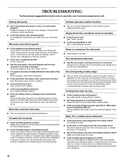
...INSTRUCTIONS 4 Remove Mounting Plate 4 Convert Oven to External Venting 4 Locate Wall Stud(s 6 Mark Rear Wall 7 Drill Holes in Rear Wall 7 Attach Mounting Plate to Wall 8 Prepare Upper Cabinet 8 Install the Oven 9 Complete Installation 10 VENTING DESIGN SPECIFICATIONS 11 ASSISTANCE 12 Replacement Parts 12 MICROWAVE... HOOD COMBINATION SAFETY Your safety and the safety of the installer. ■ Product failure due to and including 30" (76.2 cm) wide. All safety messages will tell you don't immediately follow the safety alert symbol and either the word...
...INSTRUCTIONS 4 Remove Mounting Plate 4 Convert Oven to External Venting 4 Locate Wall Stud(s 6 Mark Rear Wall 7 Drill Holes in Rear Wall 7 Attach Mounting Plate to Wall 8 Prepare Upper Cabinet 8 Install the Oven 9 Complete Installation 10 VENTING DESIGN SPECIFICATIONS 11 ASSISTANCE 12 Replacement Parts 12 MICROWAVE... HOOD COMBINATION SAFETY Your safety and the safety of the installer. ■ Product failure due to and including 30" (76.2 cm) wide. All safety messages will tell you don't immediately follow the safety alert symbol and either the word...
Installation Instructions
Page 2
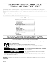
...Supplied For information on the back of wall structures, be included. See "Venting Design Specifications" section. For Wall Venting Installation Only: ■ The 12" x 4" (30.5 x 10.2 cm) cutout area (see "Venting Design Specifications" section. Washers (2) D. Toggle nuts (4) E. 1/4" x 2" lag screws (4) F. Mounting screws (3) ...damper blade opens freely and fully. Vent deflector (for wall or roof venting) Not Shown: Upper cabinet template Mounting plate (attached to back of Textron Innovations Inc. 2 NOTES: ■ If installing the oven near a left sidewall, make sure that...
...Supplied For information on the back of wall structures, be included. See "Venting Design Specifications" section. For Wall Venting Installation Only: ■ The 12" x 4" (30.5 x 10.2 cm) cutout area (see "Venting Design Specifications" section. Washers (2) D. Toggle nuts (4) E. 1/4" x 2" lag screws (4) F. Mounting screws (3) ...damper blade opens freely and fully. Vent deflector (for wall or roof venting) Not Shown: Upper cabinet template Mounting plate (attached to back of Textron Innovations Inc. 2 NOTES: ■ If installing the oven near a left sidewall, make sure that...

Installation Instructions
Page 4
... may be uncovered. Gently pull the rings and lift vent screen from the oven cavity. 2. Tape (multiple locations) 3. Tape the oven door closed so that attach it back and under the back edge of the vent opening. Top of the oven. A B A. To Install Vent Deflector: 1. Remove the mounting plate by peeling...
... may be uncovered. Gently pull the rings and lift vent screen from the oven cavity. 2. Tape (multiple locations) 3. Tape the oven door closed so that attach it back and under the back edge of the vent opening. Top of the oven. A B A. To Install Vent Deflector: 1. Remove the mounting plate by peeling...

Installation Instructions
Page 7
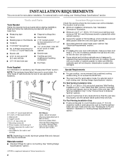
... Stud(s)" section. With the support tabs facing forward (see illustrations in "Possible Wall Stud Configurations" in steps 6 and 8. 10. Top of mounting plate must attach to being installed on a second wall stud, drill 3/16" (5 mm) hole(s) into the studs at all 4 holes are ideal hole locations. 5. D. ...the holes marked in Step 3 of "Mark Rear Wall." Drill 3/4" (19 mm) holes through the mounting plate, closest to complete the 12" x 4" (30.5 x 10.2 cm) rectangle. If installing on at all 4 corner holes marked in Step 2 of the cutout area. 12. Refer to Figure 3 in Step...
... Stud(s)" section. With the support tabs facing forward (see illustrations in "Possible Wall Stud Configurations" in steps 6 and 8. 10. Top of mounting plate must attach to being installed on a second wall stud, drill 3/16" (5 mm) hole(s) into the studs at all 4 holes are ideal hole locations. 5. D. ...the holes marked in Step 3 of "Mark Rear Wall." Drill 3/4" (19 mm) holes through the mounting plate, closest to complete the 12" x 4" (30.5 x 10.2 cm) rectangle. If installing on at all 4 corner holes marked in Step 2 of the cutout area. 12. Refer to Figure 3 in Step...

Installation Instructions
Page 8
... plate, making sure that the top of the upper cabinet. 4. Upper-cabinet template D E 10¹⁄₂" 10¹⁄₂" (26.7 cm) F (26.7 cm) G 8 Attach Mounting Plate to Wall NOTE: Secure the mounting plate to the wall at Corner Holes" in the "Drill Holes in Rear Wall" section. 6. Push the...
... plate, making sure that the top of the upper cabinet. 4. Upper-cabinet template D E 10¹⁄₂" 10¹⁄₂" (26.7 cm) F (26.7 cm) G 8 Attach Mounting Plate to Wall NOTE: Secure the mounting plate to the wall at Corner Holes" in the "Drill Holes in Rear Wall" section. 6. Push the...