User Guide
Page 5
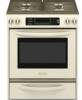
...burner knob (15,000 Btu/h) E. Left rear control knob (6000 Btu/h) E D. Right front control knob (6000 Btu/h) G. PARTS AND FEATURES This manual covers several different models. The locations and appearances of the features shown here may have purchased may not match ...Electronic oven control F G F. Oven display C. Right front control knob (6000 Btu/h) G. Right rear control knob (12,500 Btu/h) 5 The range you have some or all of your model. Electronic oven control F. Surface burner locator B. Glass Touch-Activated Electronic Oven Control Panel with Standard Burners (...
...burner knob (15,000 Btu/h) E. Left rear control knob (6000 Btu/h) E D. Right front control knob (6000 Btu/h) G. PARTS AND FEATURES This manual covers several different models. The locations and appearances of the features shown here may have purchased may not match ...Electronic oven control F G F. Oven display C. Right front control knob (6000 Btu/h) G. Right rear control knob (12,500 Btu/h) 5 The range you have some or all of your model. Electronic oven control F. Surface burner locator B. Glass Touch-Activated Electronic Oven Control Panel with Standard Burners (...
User Guide
Page 6
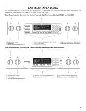
Range G H I . Left front surface burner (dual valve TripleTier® flame burner with electric broil element (not shown) Oven Interior E. Right front surface burner K. Broil burner C. Oven ... M. Model and serial number plate O. Broil element E F D. Bake burner (not visible) 6 Warming drawer (on some models) or storage drawer (on some models) B. Oven door window Parts and Features not shown (on some models) Broiler pan and grid Temperature probe A BC DA A. Oven lights B. Control panel L. Bake burner and cover (not shown...
Range G H I . Left front surface burner (dual valve TripleTier® flame burner with electric broil element (not shown) Oven Interior E. Right front surface burner K. Broil burner C. Oven ... M. Model and serial number plate O. Broil element E F D. Bake burner (not visible) 6 Warming drawer (on some models) or storage drawer (on some models) B. Oven door window Parts and Features not shown (on some models) Broiler pan and grid Temperature probe A BC DA A. Oven lights B. Control panel L. Bake burner and cover (not shown...
User Guide
Page 13
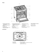
Press OPTIONS, then 3 again for only part of a minus sign means the oven will need to ... (AUTOMATIC °C CHANGE) COOKS FOOD 10°F (5°C) ...a little more 20°F (10°C) ...moderately more 30°F (15°C) ...much less To Adjust Oven Temperature Calibration: 1. A timed Sabbath Mode can also be set , only...4 to turn tones OFF. NUMBER OF RACKS RACK POSITION(S) 1 3 2 2 and 4 3 1, 3 and 5 1. The dehydrating range can be illuminated. However, some foods may give incorrect readings. Press OFF to return to clear the display. Open the oven door. 2....
Press OPTIONS, then 3 again for only part of a minus sign means the oven will need to ... (AUTOMATIC °C CHANGE) COOKS FOOD 10°F (5°C) ...a little more 20°F (10°C) ...moderately more 30°F (15°C) ...much less To Adjust Oven Temperature Calibration: 1. A timed Sabbath Mode can also be set , only...4 to turn tones OFF. NUMBER OF RACKS RACK POSITION(S) 1 3 2 2 and 4 3 1, 3 and 5 1. The dehydrating range can be illuminated. However, some foods may give incorrect readings. Press OFF to return to clear the display. Open the oven door. 2....
User Guide
Page 26
...free: 1-800-422-1230. s Installation information. To locate the KitchenAid designated service company in your area, you can write to order replacement parts, we recommend that batter is level in your nearest KitchenAid designated service center. Close the oven door all the way. ASSISTANCE... OR SERVICE Before calling for service. If you need to KitchenAid with the same precision used ? ...
...free: 1-800-422-1230. s Installation information. To locate the KitchenAid designated service company in your area, you can write to order replacement parts, we recommend that batter is level in your nearest KitchenAid designated service center. Close the oven door all the way. ASSISTANCE... OR SERVICE Before calling for service. If you need to KitchenAid with the same precision used ? ...
User Guide
Page 27
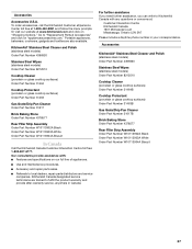
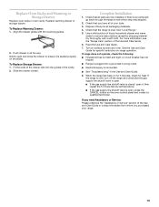
... Cooktop Protectant (porcelain or glass cooktop surfaces) Order Part Number 31463 Gas Grate/Drip Pan Cleaner Order Part Number 31617 Brick Baking Stone Order Part Number 4378577 Rear Filler Strip Assembly Order Part Number W10113902A Black Order Part Number W10113903A White Order Part Number W10113904A Biscuit In Canada Call the KitchenAid Canada Customer Interaction Centre toll free: 1-800...
... Cooktop Protectant (porcelain or glass cooktop surfaces) Order Part Number 31463 Gas Grate/Drip Pan Cleaner Order Part Number 31617 Brick Baking Stone Order Part Number 4378577 Rear Filler Strip Assembly Order Part Number W10113902A Black Order Part Number W10113903A White Order Part Number W10113904A Biscuit In Canada Call the KitchenAid Canada Customer Interaction Centre toll free: 1-800...
User Guide
Page 28
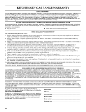
... purchase date is required to KitchenAid within 30 days from the date of purchase. 6. Service calls to the appliance. 8. Consumable parts are excluded from your home of your major appliance if it . Repairs to parts or systems resulting from unauthorized modifications...GAS RANGE WARRANTY LIMITED WARRANTY For one year from the date of purchase, when this major appliance is operated and maintained according to instructions attached to or furnished with the product, KitchenAid brand of Whirlpool Corporation or Whirlpool Canada LP (hereafter "KitchenAid") will pay for Factory Specified Parts...
... purchase date is required to KitchenAid within 30 days from the date of purchase. 6. Service calls to the appliance. 8. Consumable parts are excluded from your home of your major appliance if it . Repairs to parts or systems resulting from unauthorized modifications...GAS RANGE WARRANTY LIMITED WARRANTY For one year from the date of purchase, when this major appliance is operated and maintained according to instructions attached to or furnished with the product, KitchenAid brand of Whirlpool Corporation or Whirlpool Canada LP (hereafter "KitchenAid") will pay for Factory Specified Parts...

Installation Instructions
Page 2
...very important. All safety messages will follow instructions. TABLE OF CONTENTS RANGE SAFETY 2 INSTALLATION REQUIREMENTS 4 Tools and Parts 4 Location Requirements 4 Electrical Requirements 7 Gas Supply Requirements 7 Countertop Preparation 8 INSTALLATION INSTRUCTIONS 9 Unpack Range 9 Measure for Proper Height 9 Adjust Leveling Legs 10 Install ...antibasculement......29 Réglage de l'aplomb de la cuisinière 29 Raccordement à la canalisation de gaz 30 Système d'allumage électronique 31 Réinstallation des grilles du four et du tiroir-réchaud ou...
...very important. All safety messages will follow instructions. TABLE OF CONTENTS RANGE SAFETY 2 INSTALLATION REQUIREMENTS 4 Tools and Parts 4 Location Requirements 4 Electrical Requirements 7 Gas Supply Requirements 7 Countertop Preparation 8 INSTALLATION INSTRUCTIONS 9 Unpack Range 9 Measure for Proper Height 9 Adjust Leveling Legs 10 Install ...antibasculement......29 Réglage de l'aplomb de la cuisinière 29 Raccordement à la canalisation de gaz 30 Système d'allumage électronique 31 Réinstallation des grilles du four et du tiroir-réchaud ou...
Installation Instructions
Page 4
C A. Anti-tip bracket B. Parts needed ■ Tape measure ■ Masking tape Rear Filler Strip (optional) The filler strip may require longer screws to anchor bracket to fill a gap between the rear of the slide-in range and the wall in the kitchen. ■ ... A B A. Filler strip B. Plastic anchors (2) C. #10 x ¹⁄₂" screws (2) ■ Anti-tip bracket must be securely mounted to LP gas B ■ Level 4.8 mm) carbide-tipped masonry drill bit (for C ■ Hand or electric drill concrete/ceramic floors) ■ Hammer ■ Wrench or...
C A. Anti-tip bracket B. Parts needed ■ Tape measure ■ Masking tape Rear Filler Strip (optional) The filler strip may require longer screws to anchor bracket to fill a gap between the rear of the slide-in range and the wall in the kitchen. ■ ... A B A. Filler strip B. Plastic anchors (2) C. #10 x ¹⁄₂" screws (2) ■ Anti-tip bracket must be securely mounted to LP gas B ■ Level 4.8 mm) carbide-tipped masonry drill bit (for C ■ Hand or electric drill concrete/ceramic floors) ■ Hammer ■ Wrench or...
Installation Instructions
Page 5
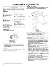
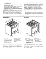
...Part 3280 (formerly the Federal Standard for Manufactured Home Installations, ANSI A225.1/NFPA 501A or with 25" (63.5 cm) countertop; A. 30 77.6 cm) B. 35⁵⁄₈" (90.5 cm) height to the floor during transit. ■ Grounded electrical supply is adequate as long as it must be available. Freestanding Range Product Dimensions Slide-in Range...require: ■ When this range is not applicable, use the Standard for Mobile Home Construction and Safety, Title 24, HUD Part 280). See "Electrical Requirements" section. ■ Proper gas supply connection must be secured ...
...Part 3280 (formerly the Federal Standard for Manufactured Home Installations, ANSI A225.1/NFPA 501A or with 25" (63.5 cm) countertop; A. 30 77.6 cm) B. 35⁵⁄₈" (90.5 cm) height to the floor during transit. ■ Grounded electrical supply is adequate as long as it must be available. Freestanding Range Product Dimensions Slide-in Range...require: ■ When this range is not applicable, use the Standard for Mobile Home Construction and Safety, Title 24, HUD Part 280). See "Electrical Requirements" section. ■ Proper gas supply connection must be secured ...
Installation Instructions
Page 9
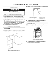
...range and gently lay it is laid on the cardboard corners. 3. Keep cardboard bottom under range. Range side frame 3. Measure the distance of the range cooktop trim to support the range...parts package from the range. Pull cardboard bottom firmly to move and install range. Measure at locations marked A, B, C, D. 9 Place them lengthwise on the floor behind the range to the floor 3. Distance from the top of range... cooktop B. Measure from the floor to underside of the range... range cooktop. Measure at all 4 ...
...range and gently lay it is laid on the cardboard corners. 3. Keep cardboard bottom under range. Range side frame 3. Measure the distance of the range cooktop trim to support the range...parts package from the range. Pull cardboard bottom firmly to move and install range. Measure at locations marked A, B, C, D. 9 Place them lengthwise on the floor behind the range to the floor 3. Distance from the top of range... cooktop B. Measure from the floor to underside of the range... range cooktop. Measure at all 4 ...
Installation Instructions
Page 12
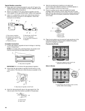
... Gas pressure regulator shutoff valve...gas to the gas pipe. Manual gas shutoff valve F. ½" or ¾" gas pipe G. Place burner grates over left front burner. Gas pressure regulator IMPORTANT: Do not remove the gas pressure regulator. 2. Check that the gas...gas supply line. The valve is open when the handle is indicated. Burner grate 6. Freestanding Models A A. Flexible connector HG F E. Burner base B. Check that connector is in the following illustration). 2. Slide... and grates from the gas pressure regulator. Gas pressure regulator B. Typical ...
... Gas pressure regulator shutoff valve...gas to the gas pipe. Manual gas shutoff valve F. ½" or ¾" gas pipe G. Place burner grates over left front burner. Gas pressure regulator IMPORTANT: Do not remove the gas pressure regulator. 2. Check that the gas...gas supply line. The valve is open when the handle is indicated. Burner grate 6. Freestanding Models A A. Flexible connector HG F E. Burner base B. Check that connector is in the following illustration). 2. Slide... and grates from the gas pressure regulator. Gas pressure regulator B. Typical ...
Installation Instructions
Page 15
... of the drawer rails into a grounded 3 prong outlet. ■ Electrical supply is an extra part, go back through the steps to see the "Range Care" section of your range. 15 If range does not operate, check the following: ■ Household fuse is intact and tight, or circuit breaker...packaging materials. 4. For more information, see which step was skipped. 2. If the range is closed . Slide the drawer closed , open it is open , press the CANCEL button on the slides. Check that the gas supply line shutoff valve is seated properly on the oven control panel and contact a ...
... of the drawer rails into a grounded 3 prong outlet. ■ Electrical supply is an extra part, go back through the steps to see the "Range Care" section of your range. 15 If range does not operate, check the following: ■ Household fuse is intact and tight, or circuit breaker...packaging materials. 4. For more information, see which step was skipped. 2. If the range is closed . Slide the drawer closed , open it is open , press the CANCEL button on the slides. Check that the gas supply line shutoff valve is seated properly on the oven control panel and contact a ...
Installation Instructions
Page 17
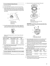
... Burners 1. Replace burner cap. 7. Remove the burner head using a size T20 TORX® screwdriver. External gas orifice spud C. Replace each Natural gas orifice spud with the correct LP gas orifice spud. 3. Place Natural gas orifice spuds in plastic parts bag for Standard Surface Burners Burner Location Burner Rating Color Size Right front Left front Right...
... Burners 1. Replace burner cap. 7. Remove the burner head using a size T20 TORX® screwdriver. External gas orifice spud C. Replace each Natural gas orifice spud with the correct LP gas orifice spud. 3. Place Natural gas orifice spuds in plastic parts bag for Standard Surface Burners Burner Location Burner Rating Color Size Right front Left front Right...

Installation Instructions
Page 19
... out. To Convert TripleTier® Flame Burner (on the side. Press nut driver down onto the gas orifice spud and remove by turning it . External gas orifice spud access plate D. Gas regulator shutoff valve (shown in the "open" position) 6. Repeat steps 1-6 for the remaining burners,... cap. 7. Burner caps B. Turn gas pressure regulator cap (marked "LP" on the external gas orifice spud. Remove plastic cover from gas pressure regulator cap. 5. Remove the plate on front of a 7 mm nut driver to help hold the gas orifice spud in plastic parts bag for the TripleTier® Flame burner...
... out. To Convert TripleTier® Flame Burner (on the side. Press nut driver down onto the gas orifice spud and remove by turning it . External gas orifice spud access plate D. Gas regulator shutoff valve (shown in the "open" position) 6. Repeat steps 1-6 for the remaining burners,... cap. 7. Burner caps B. Turn gas pressure regulator cap (marked "LP" on the external gas orifice spud. Remove plastic cover from gas pressure regulator cap. 5. Remove the plate on front of a 7 mm nut driver to help hold the gas orifice spud in plastic parts bag for the TripleTier® Flame burner...
Installation Instructions
Page 20
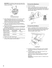
...chart for instructions. 3. Remove oven racks. 2. See "Adjust Oven Bake Flame" in plastic parts bag for each LP gas orifice spud with package containing literature. Set internal gas orifice spud aside. 5. A B A A A. The oven bake burner flame cannot be ...A. Locking screw B. Orifice hood 2. IMPORTANT: You may have yellow tips. Turn counterclockwise to change the external gas orifice spud located under the plate. Internal gas orifice spud 4. The oven broil burner flame cannot be properly adjusted if this conversion is very important. Complete ...
...chart for instructions. 3. Remove oven racks. 2. See "Adjust Oven Bake Flame" in plastic parts bag for each LP gas orifice spud with package containing literature. Set internal gas orifice spud aside. 5. A B A A A. The oven bake burner flame cannot be ...A. Locking screw B. Orifice hood 2. IMPORTANT: You may have yellow tips. Turn counterclockwise to change the external gas orifice spud located under the plate. Internal gas orifice spud 4. The oven broil burner flame cannot be properly adjusted if this conversion is very important. Complete ...
Parts Diagram
Page 1
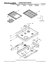
B W10168525 Rev. COOKTOP PARTS 30" Freestanding For Models: KGSS907SBL01, KGSS907SWH01, KGSS907SBT01, KGSS907SSS01 GAS OVEN (Black) (White) (Biscuit) (Stainless) CONVECTION 5−08 Litho in U.S.A. (amd) (psw) 1 Part No.
B W10168525 Rev. COOKTOP PARTS 30" Freestanding For Models: KGSS907SBL01, KGSS907SWH01, KGSS907SBT01, KGSS907SSS01 GAS OVEN (Black) (White) (Biscuit) (Stainless) CONVECTION 5−08 Litho in U.S.A. (amd) (psw) 1 Part No.
Parts Diagram
Page 2
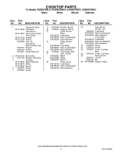
... Bracket, Mounting 4 Cooktop W10106250 Black/Stainless W10106270 White W10106260 Biscuit 5 3196537 Screw 7 3400843 Screw Illus. Part No. No. Part No. DESCRIPTION 9 9763445 Bracket, Burner 10 9756821 Support, Wiring 12 Grate, Burner Right 9761555CB Coal Black ...Black 9760225WH White 9760225BT Biscuit 18 Grate, Insert 9761557CB Coal Black 9761557SD Satin Cumberland 9761557SN Satin Moleskin Illus. No. COOKTOP PARTS For Models: KGSS907SBL01, KGSS907SWH01, KGSS907SBT01, KGSS907SSS01 (Black) (White) (Biscuit) (Stainless) Illus. DESCRIPTION 19 Cap, Burner...
... Bracket, Mounting 4 Cooktop W10106250 Black/Stainless W10106270 White W10106260 Biscuit 5 3196537 Screw 7 3400843 Screw Illus. Part No. No. Part No. DESCRIPTION 9 9763445 Bracket, Burner 10 9756821 Support, Wiring 12 Grate, Burner Right 9761555CB Coal Black ...Black 9760225WH White 9760225BT Biscuit 18 Grate, Insert 9761557CB Coal Black 9761557SD Satin Cumberland 9761557SN Satin Moleskin Illus. No. COOKTOP PARTS For Models: KGSS907SBL01, KGSS907SWH01, KGSS907SBT01, KGSS907SSS01 (Black) (White) (Biscuit) (Stainless) Illus. DESCRIPTION 19 Cap, Burner...
Parts Diagram
Page 3
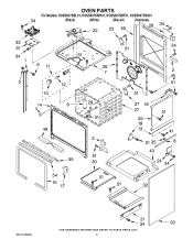
OVEN PARTS For Models: KGSS907SBL01, KGSS907SWH01, KGSS907SBT01, KGSS907SSS01 (Black) (White) (Biscuit) (Stainless) W10168525 3
OVEN PARTS For Models: KGSS907SBL01, KGSS907SWH01, KGSS907SBT01, KGSS907SSS01 (Black) (White) (Biscuit) (Stainless) W10168525 3
Parts Diagram
Page 4
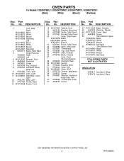
..., Chassis 27 Liner, Oven (Not serviceable) 28 9759945 Standoff, Rear 29 W10131825 Sensor 30 9756454 Bracket, GOC 31 9760223 Slide, DSI 32 W10083460 Slide, GOC 33 9762774 Central, Appliance 34 3196537 Screw 35 9760481 Washer, Insulation Body Side Trim...Stainless 55 Trim, Bottom Vent W10104890 Black W10104910 White W10104900 Biscuit W10104870 Stainless FOLLOWING PARTS NOT ILLUSTRATED INSULATION 9756817 Insulation, Wrap 9756470 Insulation, Back 4 W10168525 Part No. OVEN PARTS For Models: KGSS907SBL01, KGSS907SWH01, KGSS907SBT01, KGSS907SSS01 (Black) (White) (Biscuit) (Stainless)...
..., Chassis 27 Liner, Oven (Not serviceable) 28 9759945 Standoff, Rear 29 W10131825 Sensor 30 9756454 Bracket, GOC 31 9760223 Slide, DSI 32 W10083460 Slide, GOC 33 9762774 Central, Appliance 34 3196537 Screw 35 9760481 Washer, Insulation Body Side Trim...Stainless 55 Trim, Bottom Vent W10104890 Black W10104910 White W10104900 Biscuit W10104870 Stainless FOLLOWING PARTS NOT ILLUSTRATED INSULATION 9756817 Insulation, Wrap 9756470 Insulation, Back 4 W10168525 Part No. OVEN PARTS For Models: KGSS907SBL01, KGSS907SWH01, KGSS907SBT01, KGSS907SSS01 (Black) (White) (Biscuit) (Stainless)...

Parts Diagram
Page 5
DOOR PARTS For Models: KGSS907SBL01, KGSS907SWH01, KGSS907SBT01, KGSS907SSS01 (Black) (White) (Biscuit) (Stainless) W10168525 5
DOOR PARTS For Models: KGSS907SBL01, KGSS907SWH01, KGSS907SBT01, KGSS907SSS01 (Black) (White) (Biscuit) (Stainless) W10168525 5


