
Use & Care Guide
Page 2
... OF CONTENTS COOKTOP SAFETY 2 PARTS AND FEATURES 4 COOKTOP USE 7 Cooktop Controls 7 Cooktop Surface 8 Sealed Surface Burners 8 Even-Heat™ Grill 9 Even-Heat™ Electric Chrome Griddle 11 Cookware 12 Home Canning 12 COOKTOP CARE 12 General Cleaning 12 TROUBLESHOOTING 13 ASSISTANCE OR SERVICE 14 In the U.S.A 14 Accessories 14 In Canada...
... OF CONTENTS COOKTOP SAFETY 2 PARTS AND FEATURES 4 COOKTOP USE 7 Cooktop Controls 7 Cooktop Surface 8 Sealed Surface Burners 8 Even-Heat™ Grill 9 Even-Heat™ Electric Chrome Griddle 11 Cookware 12 Home Canning 12 COOKTOP CARE 12 General Cleaning 12 TROUBLESHOOTING 13 ASSISTANCE OR SERVICE 14 In the U.S.A 14 Accessories 14 In Canada...

Use & Care Guide
Page 4
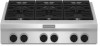
...features shown here may have some models) F. Culinary ledge C. Even-Heat™ grill (on griddle models) Not shown: Optional 9" (22.9 cm), 22" (55.9 cm) and adjustable backguards Optional griddle cover Optional grill cover Optional wok ring Optional stainless steel knobs Control Panels KGCU407 F E G... single grate design D. Drip tray (on some models) E. D C F E B A G A. Island trim G. Even-Heat™ electric chrome griddle (on some or all of your model. PARTS AND FEATURES This manual covers several different models. The cooktop you have purchased may not match those...
...features shown here may have some models) F. Culinary ledge C. Even-Heat™ grill (on griddle models) Not shown: Optional 9" (22.9 cm), 22" (55.9 cm) and adjustable backguards Optional griddle cover Optional grill cover Optional wok ring Optional stainless steel knobs Control Panels KGCU407 F E G... single grate design D. Drip tray (on some models) E. D C F E B A G A. Island trim G. Even-Heat™ electric chrome griddle (on some or all of your model. PARTS AND FEATURES This manual covers several different models. The cooktop you have purchased may not match those...

Use & Care Guide
Page 5
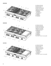
...burner I . 5,000 Btu/h burner J. 15,000 Btu/h burner J K L A. Left rear control knob B. Even-Heat™ electric chrome griddle I . 15,000 Btu/h burner J. 5,000 Btu/h burner K. 15,000 Btu/h burner L. 20,000 Btu/h burner 5 Left front control ... knob F. 20,000 Btu/h burner G. 15,000 Btu/h burner H. Left front control knob C. Center rear control knob D.Center front control knob E. Left rear control knob B. Griddle control knob D. Right front control knob F. 20,000 Btu/h burner G. 15,000 Btu/h burner I J A B C D E F A. Right rear control knob F. KGCU462 H G F A ...
...burner I . 5,000 Btu/h burner J. 15,000 Btu/h burner J K L A. Left rear control knob B. Even-Heat™ electric chrome griddle I . 15,000 Btu/h burner J. 5,000 Btu/h burner K. 15,000 Btu/h burner L. 20,000 Btu/h burner 5 Left front control ... knob F. 20,000 Btu/h burner G. 15,000 Btu/h burner H. Left front control knob C. Center rear control knob D.Center front control knob E. Left rear control knob B. Griddle control knob D. Right front control knob F. 20,000 Btu/h burner G. 15,000 Btu/h burner I J A B C D E F A. Right rear control knob F. KGCU462 H G F A ...
Use & Care Guide
Page 6
... Right front control knob F. Left rear control knob B. Griddle control knob G. 20,000 Btu/h H. 15,000 Btu/h I . 15,000 Btu/h J. Center rear control knob E. Left rear control knob B. Even-Heat™ electric chrome griddle A. Right rear control knob E. Grill control knob D. ...Right front control knob G. Even-Heat™ electric chrome griddle Right front control knob H. 20,000 Btu/h I . Center rear control knob D. Griddle control knob H. 20,000 Btu/h I JK L AB C DE F 6 A. Center front control knob F. Even-Heat™ ...
... Right front control knob F. Left rear control knob B. Griddle control knob G. 20,000 Btu/h H. 15,000 Btu/h I . 15,000 Btu/h J. Center rear control knob E. Left rear control knob B. Even-Heat™ electric chrome griddle A. Right rear control knob E. Grill control knob D. ...Right front control knob G. Even-Heat™ electric chrome griddle Right front control knob H. 20,000 Btu/h I . Center rear control knob D. Griddle control knob H. 20,000 Btu/h I JK L AB C DE F 6 A. Center front control knob F. Even-Heat™ ...

Use & Care Guide
Page 11
...a nylon scrub pad with soapy water and rinse with hot, soapy water prior to desired temperature. 3. The griddle light will turn off when the griddle has finished preheating. Place food on the griddle and cook to preheat for individual tastes. FOOD SETTING COOK TIME TOTAL MINUTES Sausage patties and links 325°... Breasts, boneless MED-LO MED 50-80 20-40 Fish Steaks ³⁄₄ - 1" (1.9-2.5 cm) MED 10-15 Even-Heat™ Chrome Electric Griddle (on a hot griddle may need to remove excess grease and oil. 11 Position the drip tray under the front edge of the...
...a nylon scrub pad with soapy water and rinse with hot, soapy water prior to desired temperature. 3. The griddle light will turn off when the griddle has finished preheating. Place food on the griddle and cook to preheat for individual tastes. FOOD SETTING COOK TIME TOTAL MINUTES Sausage patties and links 325°... Breasts, boneless MED-LO MED 50-80 20-40 Fish Steaks ³⁄₄ - 1" (1.9-2.5 cm) MED 10-15 Even-Heat™ Chrome Electric Griddle (on a hot griddle may need to remove excess grease and oil. 11 Position the drip tray under the front edge of the...

Use & Care Guide
Page 13
... abrasive paper towels. Oven mitts may have been used ? To avoid damage to a setting. ■ Are the burner ports clogged? GRIDDLE MODULE Clean the griddle shortly after removing food and the griddle has cooled down. Surface burner makes popping noises ■ Is the burner wet? The appliance may be worn while cleaning. ■...
... abrasive paper towels. Oven mitts may have been used ? To avoid damage to a setting. ■ Are the burner ports clogged? GRIDDLE MODULE Clean the griddle shortly after removing food and the griddle has cooled down. Surface burner makes popping noises ■ Is the burner wet? The appliance may be worn while cleaning. ■...

Use & Care Guide
Page 14
... not light ■ Is there continuous sparking, but the burner does not light? Preheat grill or griddle. To locate the KitchenAid designated service company in your area, call the KitchenAid Customer eXperience Center toll free at www.kitchenaid.com and click on our full line of the surface burner and contact a service technician. For...
... not light ■ Is there continuous sparking, but the burner does not light? Preheat grill or griddle. To locate the KitchenAid designated service company in your area, call the KitchenAid Customer eXperience Center toll free at www.kitchenaid.com and click on our full line of the surface burner and contact a service technician. For...
Installation Guide
Page 4
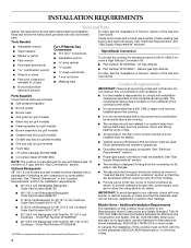
... the cooktop. ■ The cooktop should be located as windows, doors and strong heating vents or fans. ■ Grease trays (2) (on grill models) ■ Griddle drip tray (on griddle models) ■ Grill drip tray (on grill models) ■ Foam tape ■ LP orifice package (W10221288) ■ All openings in the wall or...
... the cooktop. ■ The cooktop should be located as windows, doors and strong heating vents or fans. ■ Grease trays (2) (on grill models) ■ Griddle drip tray (on griddle models) ■ Grill drip tray (on grill models) ■ Foam tape ■ LP orifice package (W10221288) ■ All openings in the wall or...

Installation Guide
Page 10
.... Must be different, according to the smaller thread ends of the flexible connector adapters (see "Install Grill Grease Trays" or "Install Griddle" section. 10 Install the pressure regulator with Natural and LP gas. Do not make connections to the pressure regulator using a ¹⁄...regulator and cause a gas leak. A B C A B C D A. NOTE: Check that connector is parallel to turn on your model has a grill or griddle, see B and F in the "Complete Installation" section. 6. Apply pipe-joint compound made for use with arrow pointing up to the front edge of pipe fittings...
.... Must be different, according to the smaller thread ends of the flexible connector adapters (see "Install Grill Grease Trays" or "Install Griddle" section. 10 Install the pressure regulator with Natural and LP gas. Do not make connections to the pressure regulator using a ¹⁄...regulator and cause a gas leak. A B C A B C D A. NOTE: Check that connector is parallel to turn on your model has a grill or griddle, see B and F in the "Complete Installation" section. 6. Apply pipe-joint compound made for use with arrow pointing up to the front edge of pipe fittings...

Installation Guide
Page 12
... contact the dealer from the control console. Remove the control knobs. 4. A A. Grill indicator light connector 12 Install Griddle (on griddle models) The griddle is plugged in and the circuit breaker has not tripped or the fuse has not blown. ■ Check that the...cooktop flame should light within 4 seconds. Dual Flame Burner A B A. Upper flame B B. Lower (simmer) flame Single Flame Burner A. Griddle drip tray B. Complete Installation Electronic Ignition System Initial lighting and gas flame adjustments Cooktop burners use electronic igniters in the middle with one arm and...
... contact the dealer from the control console. Remove the control knobs. 4. A A. Grill indicator light connector 12 Install Griddle (on griddle models) The griddle is plugged in and the circuit breaker has not tripped or the fuse has not blown. ■ Check that the...cooktop flame should light within 4 seconds. Dual Flame Burner A B A. Upper flame B B. Lower (simmer) flame Single Flame Burner A. Griddle drip tray B. Complete Installation Electronic Ignition System Initial lighting and gas flame adjustments Cooktop burners use electronic igniters in the middle with one arm and...

Installation Guide
Page 13
...into place on each setting. Replace the control knobs. 23. Plug in the cutout. 22. Repeat steps 8 through 15 for any other hand. 13. Griddle switch connectors 7. Remove the control knob. 12. Tighten screw to adjust. Flush with the top edge of valve) B. Replace the 2 screws on the ...cooktop. A B A. Replace the round gasket. 16. Support the control console in the middle with one arm and disconnect the griddle switch connectors and the grill indicator light with the other burners that the control console is flush with top of the control console. 21. A B ...
...into place on each setting. Replace the control knobs. 23. Plug in the cutout. 22. Repeat steps 8 through 15 for any other hand. 13. Griddle switch connectors 7. Remove the control knob. 12. Tighten screw to adjust. Flush with the top edge of valve) B. Replace the 2 screws on the ...cooktop. A B A. Replace the round gasket. 16. Support the control console in the middle with one arm and disconnect the griddle switch connectors and the grill indicator light with the other burners that the control console is flush with top of the control console. 21. A B ...

Installation Guide
Page 18
... shutoff valve in the "Complete Installation" section for properly connecting the cooktop to the gas pipe. REMEMBER: Once you have a slightly yellow tip. 3. A A. STRIP CIRCUITS Griddle 120V Control Wiring Diagram To Cooktop Stand-Alone R P2-1 P1-1 OR/W 1320W/120V OR/W Lamp 120V BU W Rotary Control P1-3 W P1-4 V W RTD W WV V W P2-6 P1...
... shutoff valve in the "Complete Installation" section for properly connecting the cooktop to the gas pipe. REMEMBER: Once you have a slightly yellow tip. 3. A A. STRIP CIRCUITS Griddle 120V Control Wiring Diagram To Cooktop Stand-Alone R P2-1 P1-1 OR/W 1320W/120V OR/W Lamp 120V BU W Rotary Control P1-3 W P1-4 V W RTD W WV V W P2-6 P1...

Installation Guide
Page 19
... Burner Temperature Sensor Heating Element Indicator Lamp 19 Verify proper operation after servicing. 6 Burners Cooktop Reignition Wiring Diagram Electrodes Output Control Input G R R R BU R BR R Y R G R BK R R Griddle Spare W BK BK Grill Spare W Power Cord L N R W BK W GND R GND Main - WIRING DIAGRAMS Caution: Label all wires prior to disconnection when servicing controls. Harness Power...
... Burner Temperature Sensor Heating Element Indicator Lamp 19 Verify proper operation after servicing. 6 Burners Cooktop Reignition Wiring Diagram Electrodes Output Control Input G R R R BU R BR R Y R G R BK R R Griddle Spare W BK BK Grill Spare W Power Cord L N R W BK W GND R GND Main - WIRING DIAGRAMS Caution: Label all wires prior to disconnection when servicing controls. Harness Power...

Installation Guide
Page 20
Gas Burner Temperature Sensor Heating Element Indicator Lamp 20 Harness Power Spare L BR N Y 4 3 Cooktop Front View Power Cord Only To Cooktop Stand Alone Version LEGEND Ground Plug With Receptacle (Chassis) Female With Male Connector Connector Electrode Transformer Relay Contacts Solenoid Valve Switch Cooktop RTD - 4 Burner Cooktop Reignition Wiring Diagram Electrodes Output Control Input G R R R BU R BR R Y SW1 SW2 R SW3 SW4 BU 2 1 R Griddle Spare W BK BK Grill Spare W Power Cord L N R W BK W R GND R GND Main -
Gas Burner Temperature Sensor Heating Element Indicator Lamp 20 Harness Power Spare L BR N Y 4 3 Cooktop Front View Power Cord Only To Cooktop Stand Alone Version LEGEND Ground Plug With Receptacle (Chassis) Female With Male Connector Connector Electrode Transformer Relay Contacts Solenoid Valve Switch Cooktop RTD - 4 Burner Cooktop Reignition Wiring Diagram Electrodes Output Control Input G R R R BU R BR R Y SW1 SW2 R SW3 SW4 BU 2 1 R Griddle Spare W BK BK Grill Spare W Power Cord L N R W BK W R GND R GND Main -


