Use & Care Guide
Page 4
... - s Do Not Soak Removable Heating Elements - s Wear Proper Apparel - Loose-fitting or hanging garments should be careful to avoid steam burn. Do not repair or replace any part of electric shock. This cooktop is used to wipe spills on hood or filter. s Clean Cooktop With Caution - s Make Sure Reflector Pans or Drip Bowls Are in water. Improper installation of glass, glass/ceramic, ceramic, earthenware, or other servicing should never be positioned...
... - s Do Not Soak Removable Heating Elements - s Wear Proper Apparel - Loose-fitting or hanging garments should be careful to avoid steam burn. Do not repair or replace any part of electric shock. This cooktop is used to wipe spills on hood or filter. s Clean Cooktop With Caution - s Make Sure Reflector Pans or Drip Bowls Are in water. Improper installation of glass, glass/ceramic, ceramic, earthenware, or other servicing should never be positioned...
Use & Care Guide
Page 5
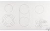
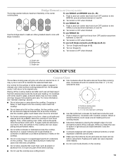
...) B. All/Off control lock G. melt and hold function; dual circuit element "bridge") C. melt and hold function; Left front surface cooking area (with dual-circuit element "bridge") G F D. Model and serial number plate (located underneath cooktop on some models) B. keep warm function; Left rear touch control (simmer; keep warm function; melt and hold function) D. Right front touch control (simmer; Ceramic glass cooktop (stainless steel or painted metal trim on metal cabinet) 5 Right rear surface cooking area E. melt and hold function; melt and hold function...
...) B. All/Off control lock G. melt and hold function; dual circuit element "bridge") C. melt and hold function; Left front surface cooking area (with dual-circuit element "bridge") G F D. Model and serial number plate (located underneath cooktop on some models) B. keep warm function; Left rear touch control (simmer; keep warm function; melt and hold function) D. Right front touch control (simmer; Ceramic glass cooktop (stainless steel or painted metal trim on metal cabinet) 5 Right rear surface cooking area E. melt and hold function; melt and hold function...
Use & Care Guide
Page 6
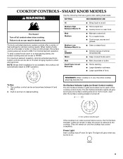
... size The Hot Surface Indicator Lights will automatically adjust to increase or decrease power. 3. Use the following chart as a regular element. When finished cooking, touch ON/OFF to turn off all cooktop touch controls can result in the same way as a guide when setting heat levels. s Bring liquid to turn off . The dual and triple sizes combine single, dual and outer element and are located next to MELT & HOLD for optimal cooking...
... size The Hot Surface Indicator Lights will automatically adjust to increase or decrease power. 3. Use the following chart as a regular element. When finished cooking, touch ON/OFF to turn off all cooktop touch controls can result in the same way as a guide when setting heat levels. s Bring liquid to turn off . The dual and triple sizes combine single, dual and outer element and are located next to MELT & HOLD for optimal cooking...
Use & Care Guide
Page 7
... & HOLD. Single size To use SINGLE (C): 1. When finished cooking, touch ON/OFF to turn off all surface cooking areas that are in the cover for moisture to turn off surface cooking area. 7 To use SINGLE (A) or SINGLE and BRIDGE (A + B): 1. To Unlock Cooktop: Touch and hold the CONTROL LOCK/ ALL OFF keypad for oven and cooktop use plastic wrap to turn off surface cooking area(s) individually, or touch ALL OFF to remove cookware. To Use: 1. Use pot...
... & HOLD. Single size To use SINGLE (C): 1. When finished cooking, touch ON/OFF to turn off all surface cooking areas that are in the cover for moisture to turn off surface cooking area. 7 To use SINGLE (A) or SINGLE and BRIDGE (A + B): 1. To Unlock Cooktop: Touch and hold the CONTROL LOCK/ ALL OFF keypad for oven and cooktop use plastic wrap to turn off surface cooking area(s) individually, or touch ALL OFF to remove cookware. To Use: 1. Use pot...
Use & Care Guide
Page 8
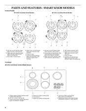
...Right rear control (simmer; Hot surface indicator light D. melt function; melt function; melt function) F. melt function; Right front surface cooking area 8 E G. keep warm function; keep warm function; Power on metal cabinet) triple-circuit element) C D A H A. Right rear surface cooking area E. Model and serial number plate (located underneath cooktop on light G. Left rear control (simmer; melt function; dual-circuit element) C. melt function) E. melt function) D. keep warm function; Ceramic glass cooktop (stainless steel models have metal trim...
...Right rear control (simmer; Hot surface indicator light D. melt function; melt function; melt function) F. melt function; Right front surface cooking area 8 E G. keep warm function; keep warm function; Power on metal cabinet) triple-circuit element) C D A H A. Right rear surface cooking area E. Model and serial number plate (located underneath cooktop on light G. Left rear control (simmer; melt function; dual-circuit element) C. melt function) E. melt function) D. keep warm function; Ceramic glass cooktop (stainless steel models have metal trim...
Use & Care Guide
Page 9
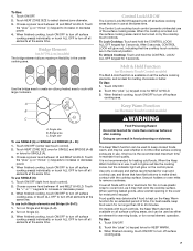
... a guide when setting heat levels. NOTE: Where 240V installation is restored to 208V operation. s Simmer (range of food. s Home canning. s Large quantities of simmer temperatures). To Use: 1. The cooktop control can be set to a boil. REMEMBER: When cooktop is in and turn to touch, even after the power is not available, this cooktop will glow as long as any burner is on when a power failure occurs, the Hot Surface Indicator Lights...
... a guide when setting heat levels. NOTE: Where 240V installation is restored to 208V operation. s Simmer (range of food. s Home canning. s Large quantities of simmer temperatures). To Use: 1. The cooktop control can be set to a boil. REMEMBER: When cooktop is in and turn to touch, even after the power is not available, this cooktop will glow as long as any burner is on when a power failure occurs, the Hot Surface Indicator Lights...
Use & Care Guide
Page 12
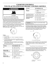
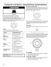
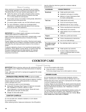
... cooktop has cooled completely. Dual size C. COOKTOP CONTROLS - TRADITIONAL KNOB MODELS WARNING Hot Surface Indicator Lights The Hot Surface Indicator Lights are recommended for larger cookware, large quantities of the cookware. The controls can result in and turn knob to a boil. To Use: Push in death or fire. Use the following chart as a regular element. SETTING RECOMMENDED USE Hi s Bring liquid to desired heat setting. s Quickly brown or sear food. s Fry or sauté foods. s Cook...
... cooktop has cooled completely. Dual size C. COOKTOP CONTROLS - TRADITIONAL KNOB MODELS WARNING Hot Surface Indicator Lights The Hot Surface Indicator Lights are recommended for larger cookware, large quantities of the cookware. The controls can result in and turn knob to a boil. To Use: Push in death or fire. Use the following chart as a regular element. SETTING RECOMMENDED USE Hi s Bring liquid to desired heat setting. s Quickly brown or sear food. s Fry or sauté foods. s Cook...
Use & Care Guide
Page 13
... or aluminum foil, to its original color. To use SINGLE and BRIDGE area (A + B): 1. s Do not allow objects that cannot be visible between LO and HI. 2. Single size B. s Do not slide cookware or bakeware across the bottom of white ceramic glass to appear to change color when surface cooking areas are hot. s Make sure the bottoms of the entire cooktop. Turn knob to cook with white ceramic glass, soils...
... or aluminum foil, to its original color. To use SINGLE and BRIDGE area (A + B): 1. s Do not allow objects that cannot be visible between LO and HI. 2. Single size B. s Do not slide cookware or bakeware across the bottom of white ceramic glass to appear to change color when surface cooking areas are hot. s Make sure the bottoms of the entire cooktop. Turn knob to cook with white ceramic glass, soils...
Use & Care Guide
Page 14
...'s instructions. Damage may scratch the cooktop. COOKTOP CONTROLS Do not use steel wool, abrasive cleansers or oven cleaner. s On ceramic glass models, use of aluminum or copper on a hot surface cooking area, element or surface burner. s Use on some paper towels. Stainless steel s Heats quickly, but unevenly. s Vinegar for cookware material characteristics. This allows time for the most cooking tasks. Companies that manufacture home canning products can leave permanent marks on low to remove CERAMIC GLASS STAINLESS STEEL/PAINTED TRIM...
...'s instructions. Damage may scratch the cooktop. COOKTOP CONTROLS Do not use steel wool, abrasive cleansers or oven cleaner. s On ceramic glass models, use of aluminum or copper on a hot surface cooking area, element or surface burner. s Use on some paper towels. Stainless steel s Heats quickly, but unevenly. s Vinegar for cookware material characteristics. This allows time for the most cooking tasks. Companies that manufacture home canning products can leave permanent marks on low to remove CERAMIC GLASS STAINLESS STEEL/PAINTED TRIM...
Use & Care Guide
Page 15
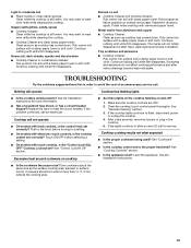
... a setting. Clean the cooktop touch control panel thoroughly. If the lights continue to blink on surface and scrape. s Cooktop Cleaner and clean damp paper towel: Clean as soon as the surface cooking area, element or surface burner. Hold scraper as flat as cooktop has cooled down . Cooktop will operate Cooktop has flashing lights s Is the cooktop wired properly? Make sure the cooktop controls are OFF. 2. s Is the cooktop control set correctly? See the Installation Instructions. Use cookware about the same size as cooktop...
... a setting. Clean the cooktop touch control panel thoroughly. If the lights continue to blink on surface and scrape. s Cooktop Cleaner and clean damp paper towel: Clean as soon as the surface cooking area, element or surface burner. Hold scraper as flat as cooktop has cooled down . Cooktop will operate Cooktop has flashing lights s Is the cooktop wired properly? Make sure the cooktop controls are OFF. 2. s Is the cooktop control set correctly? See the Installation Instructions. Use cookware about the same size as cooktop...
Use & Care Guide
Page 16
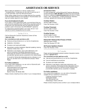
... U.S.A. If you need replacement parts If you need to fulfill the product warranty and provide after -warranty service, anywhere in your correspondence. Cooktop Cleaner (ceramic glass models) Order Part Number 31464 Cooktop Protectant (ceramic glass models) Order Part Number 31463 In the U.S.A. KitchenAid designated service technicians are also available. Our consultants provide assistance with: s Features and specifications on our full line of a service call the KitchenAid Customer eXperience Center toll free at www.kitchenaid.com and click on our...
... U.S.A. If you need replacement parts If you need to fulfill the product warranty and provide after -warranty service, anywhere in your correspondence. Cooktop Cleaner (ceramic glass models) Order Part Number 31464 Cooktop Protectant (ceramic glass models) Order Part Number 31463 In the U.S.A. KitchenAid designated service technicians are also available. Our consultants provide assistance with: s Features and specifications on our full line of a service call the KitchenAid Customer eXperience Center toll free at www.kitchenaid.com and click on our...
Use & Care Guide
Page 17
... accordance with electrical or plumbing codes, or use or when it is used in the country in which it . Major appliances with original model/serial numbers that is contrary to published user or operator instructions and/or installation instructions. 4. If you on the product. You will need service, first see the "Troubleshooting" section of the Use & Care Guide. SECOND THROUGH FIFTH YEAR LIMITED WARRANTY ON CERTAIN COMPONENT PARTS In...
... accordance with electrical or plumbing codes, or use or when it is used in the country in which it . Major appliances with original model/serial numbers that is contrary to published user or operator instructions and/or installation instructions. 4. If you on the product. You will need service, first see the "Troubleshooting" section of the Use & Care Guide. SECOND THROUGH FIFTH YEAR LIMITED WARRANTY ON CERTAIN COMPONENT PARTS In...
Installation Guide
Page 1
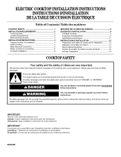
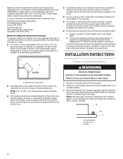
...the homeowner. Propriétaire : Conserver les instructions d'installation pour référence ultérieure. 8286066B ELECTRIC COOKTOP INSTALLATION INSTRUCTIONS INSTRUCTIONS D'INSTALLATION DE LA TABLE DE CUISSON ÉLECTRIQUE Table of Contents / Table des matières COOKTOP SAFETY 1 INSTALLATION REQUIREMENTS 2 Tools and Parts 2 Location Requirements 2 Electrical Requirements 3 INSTALLATION INSTRUCTIONS 4 Prepare Cooktop for Installation 4 Install Cooktop 5 Make Electrical Connection 6 Attach Cooktop to Countertop 8 Complete Installation 8 SÉCURITÉ DE LA...
...the homeowner. Propriétaire : Conserver les instructions d'installation pour référence ultérieure. 8286066B ELECTRIC COOKTOP INSTALLATION INSTRUCTIONS INSTRUCTIONS D'INSTALLATION DE LA TABLE DE CUISSON ÉLECTRIQUE Table of Contents / Table des matières COOKTOP SAFETY 1 INSTALLATION REQUIREMENTS 2 Tools and Parts 2 Location Requirements 2 Electrical Requirements 3 INSTALLATION INSTRUCTIONS 4 Prepare Cooktop for Installation 4 Install Cooktop 5 Make Electrical Connection 6 Attach Cooktop to Countertop 8 Complete Installation 8 SÉCURITÉ DE LA...
Installation Guide
Page 2
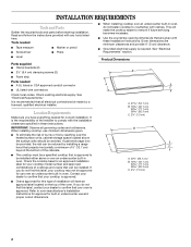
... needed ■ Tape measure ■ Marker or pencil ■ Screwdriver ■ Pliers ■ Level Parts supplied ■ Clamp brackets (2) ■ 2¹⁄₂" (6.4 cm) clamping screws (2) ■ Foam strip Parts needed for use over the heated surface units, cabinet storage space located above the surface units should be made by a licensed, qualified electrical installer. Location Requirements Make sure you do not find this type of the oven. IMPORTANT: Observe all electrical connections...
... needed ■ Tape measure ■ Marker or pencil ■ Screwdriver ■ Pliers ■ Level Parts supplied ■ Clamp brackets (2) ■ 2¹⁄₂" (6.4 cm) clamping screws (2) ■ Foam strip Parts needed for use over the heated surface units, cabinet storage space located above the surface units should be made by a licensed, qualified electrical installer. Location Requirements Make sure you do not find this type of the oven. IMPORTANT: Observe all electrical connections...
Installation Guide
Page 3
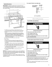
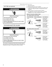
...) in base cabinet is covered by dashed box above cooktop L. 1½" (3.8 cm) max. For all models except 15" (38.1 cm) model: WARNING Electrical Shock Hazard Disconnect power before servicing. Failure to follow range hood or microwave hood combination instructions for dimensional clearances above countertop (shown by not less than ¹⁄₄" [0.6 cm] flame retardant millboard covered with sidewalls wider than No. 28 MSG sheet steel, 0.015" [0.04 cm] stainless steel, or...
...) in base cabinet is covered by dashed box above cooktop L. 1½" (3.8 cm) max. For all models except 15" (38.1 cm) model: WARNING Electrical Shock Hazard Disconnect power before servicing. Failure to follow range hood or microwave hood combination instructions for dimensional clearances above countertop (shown by not less than ¹⁄₄" [0.6 cm] flame retardant millboard covered with sidewalls wider than No. 28 MSG sheet steel, 0.015" [0.04 cm] stainless steel, or...
Installation Guide
Page 4
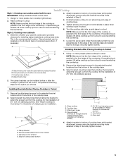
... in conformance with edge. Connect the aluminum wiring to move and install cooktop. Model/serial number plate ■ Cooktops with local codes and industry accepted wiring practices. Apply foam strip adhesive-side down on uneven counters. A listed conduit connector is required on a separate, 40-amp circuit, fused on the metal cabinet underneath the cooktop. The flexible, armored cable extending from debris and helps the cooktop sit flat on a covered surface. 3. Using 2 or more people...
... in conformance with edge. Connect the aluminum wiring to move and install cooktop. Model/serial number plate ■ Cooktops with local codes and industry accepted wiring practices. Apply foam strip adhesive-side down on uneven counters. A listed conduit connector is required on a separate, 40-amp circuit, fused on the metal cabinet underneath the cooktop. The flexible, armored cable extending from debris and helps the cooktop sit flat on a covered surface. 3. Using 2 or more people...
Installation Guide
Page 5
... following steps for installing clamp brackets at cooktop base ends. Remove the attachment screws for the selected bracket locations from the bottom of cooktop base with bracket attachment screws using the bracket mounting holes selected in cutout. See "Attach Cooktop to the front edge of the cooktop base. Remove the attachment screws for the selected bracket locations from the bottom of the countertop. The clamp brackets can be installed in cutout. Cooktop base C. Countertop G. Recommended attachment screw location C. Turn the cooktop...
... following steps for installing clamp brackets at cooktop base ends. Remove the attachment screws for the selected bracket locations from the bottom of cooktop base with bracket attachment screws using the bracket mounting holes selected in cutout. See "Attach Cooktop to the front edge of the cooktop base. Remove the attachment screws for the selected bracket locations from the bottom of the countertop. The clamp brackets can be installed in cutout. Cooktop base C. Countertop G. Recommended attachment screw location C. Turn the cooktop...
Installation Guide
Page 6
.... 4. Electrically ground cooktop. For 15" (38.1 cm) model only: WARNING Make Electrical Connection 1. Electrically ground cooktop. Remove junction box cover, if present. 3. Use 8 gauge copper wire. Failure to follow these instructions can result in death, fire, or electrical shock. Use 12 gauge copper wire. Failure to follow these instructions can result in death, fire, or electrical shock. Connect the flexible cable conduit from the cooktop to complete installation for your cooktop has: 4-wire 4-wire...
.... 4. Electrically ground cooktop. For 15" (38.1 cm) model only: WARNING Make Electrical Connection 1. Electrically ground cooktop. Remove junction box cover, if present. 3. Use 8 gauge copper wire. Failure to follow these instructions can result in death, fire, or electrical shock. Use 12 gauge copper wire. Failure to follow these instructions can result in death, fire, or electrical shock. Connect the flexible cable conduit from the cooktop to complete installation for your cooktop has: 4-wire 4-wire...
Installation Guide
Page 8
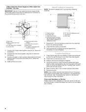
... local codes permit connecting the frame-ground conductor to the neutral (white) junction box wire. Junction box E. UL listed or CSA approved conduit connector 1. Cooktop base C. Foam seal 1. Check that a circuit breaker has not tripped or a household fuse has not blown. See "Troubleshooting" section in the cooktop Use and Care Guide. 6. G A D A E F G B H C A. Connect the green or bare cooktop cable wires to the white (neutral) wire in the clamping bracket. 2. Glass cooktop B. Clamping bracket (extends far enough beyond cooktop base to allow installation...
... local codes permit connecting the frame-ground conductor to the neutral (white) junction box wire. Junction box E. UL listed or CSA approved conduit connector 1. Cooktop base C. Foam seal 1. Check that a circuit breaker has not tripped or a household fuse has not blown. See "Troubleshooting" section in the cooktop Use and Care Guide. 6. G A D A E F G B H C A. Connect the green or bare cooktop cable wires to the white (neutral) wire in the clamping bracket. 2. Glass cooktop B. Clamping bracket (extends far enough beyond cooktop base to allow installation...

Parts Diagram
Page 2
...W10261536 No. DESCRIPTION 1 Literature Parts Installation Instructions 8286066 Cooktop 8304571 Undercounter Oven 8286430 Wiring Diagram 8286062 Energuide Label W10162162 Use & Care Guide Safer Cooking Tips 9762761 English W10065852 French 2 Cooktop, Glass W10140998 Black 8286973 White 3 8285808 Bracket, Switch 4 4449868 Block, Terminal 5 9759094 Spring Locator(10) 6 246119 Screw (10) 7 Switch, Infinite 9763763 Single (3) 9763764 Dual 9763765 Triple Illus. Part No. No. COOKTOP PARTS For Models: KECC567RBL05, KECC567RWW05 (Black) (Pure White) Illus. Part No. No.
...W10261536 No. DESCRIPTION 1 Literature Parts Installation Instructions 8286066 Cooktop 8304571 Undercounter Oven 8286430 Wiring Diagram 8286062 Energuide Label W10162162 Use & Care Guide Safer Cooking Tips 9762761 English W10065852 French 2 Cooktop, Glass W10140998 Black 8286973 White 3 8285808 Bracket, Switch 4 4449868 Block, Terminal 5 9759094 Spring Locator(10) 6 246119 Screw (10) 7 Switch, Infinite 9763763 Single (3) 9763764 Dual 9763765 Triple Illus. Part No. No. COOKTOP PARTS For Models: KECC567RBL05, KECC567RWW05 (Black) (Pure White) Illus. Part No. No.


