Installation Guide
Page 1
...symbol and either the word "DANGER" or "WARNING." Installer: Leave installation instructions with the homeowner. ELECTRIC COOKTOP INSTALLATION INSTRUCTIONS INSTRUCTIONS D'INSTALLATION DE LA TABLE DE CUISSON ÉLECTRIQUE Table of Contents / Table des matières COOKTOP SAFETY 1 INSTALLATION REQUIREMENTS 2 Tools and Parts 2 Location Requirements 2 Electrical Requirements 3 INSTALLATION INSTRUCTIONS 4 Prepare Cooktop for Installation 4 Install Cooktop 5 Make Electrical Connection 6 Attach Cooktop to Countertop 8 Complete Installation 8 SÉCURITÉ DE LA TABLE DE CUISSON...
...symbol and either the word "DANGER" or "WARNING." Installer: Leave installation instructions with the homeowner. ELECTRIC COOKTOP INSTALLATION INSTRUCTIONS INSTRUCTIONS D'INSTALLATION DE LA TABLE DE CUISSON ÉLECTRIQUE Table of Contents / Table des matières COOKTOP SAFETY 1 INSTALLATION REQUIREMENTS 2 Tools and Parts 2 Location Requirements 2 Electrical Requirements 3 INSTALLATION INSTRUCTIONS 4 Prepare Cooktop for Installation 4 Install Cooktop 5 Make Electrical Connection 6 Attach Cooktop to Countertop 8 Complete Installation 8 SÉCURITÉ DE LA TABLE DE CUISSON...
Installation Guide
Page 2
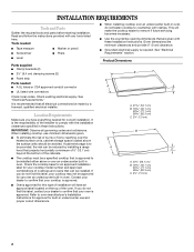
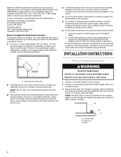
... required. IMPORTANT: Observe all electrical connections be avoided. Tools needed ■ Tape measure ■ Marker or pencil ■ Screwdriver ■ Pliers ■ Level Parts supplied ■ Clamp brackets (2) ■ 2¹⁄₂" (6.4 cm) clamping screws (2) ■ Foam strip Parts needed for use over an undercounter built-in oven. When installing cooktop, use and proper cutout dimensions. ■ When installing cooktop over an undercounter built-in oven, do not find this label, contact your cooktop model number...
... required. IMPORTANT: Observe all electrical connections be avoided. Tools needed ■ Tape measure ■ Marker or pencil ■ Screwdriver ■ Pliers ■ Level Parts supplied ■ Clamp brackets (2) ■ 2¹⁄₂" (6.4 cm) clamping screws (2) ■ Foam strip Parts needed for use over an undercounter built-in oven. When installing cooktop, use and proper cutout dimensions. ■ When installing cooktop over an undercounter built-in oven, do not find this label, contact your cooktop model number...
Installation Guide
Page 3
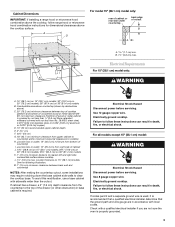
... microwave hood combination instructions for dimensional clearances above the cooktop surface. If cabinet has a drawer, a 3" (7.6 cm) depth clearance from bottom of wood or metal cabinet is covered by not less than ¹⁄₄" [0.6 cm] flame retardant millboard covered with local codes. Use 12 gauge copper wire. Junction box or outlet; 12" (30.5 cm) minimum from the countertop to clear the cooktop base. counter thickness on 36" (91.4 cm) models B. Cabinet Dimensions IMPORTANT: If installing a range hood...
... microwave hood combination instructions for dimensional clearances above the cooktop surface. If cabinet has a drawer, a 3" (7.6 cm) depth clearance from bottom of wood or metal cabinet is covered by not less than ¹⁄₄" [0.6 cm] flame retardant millboard covered with local codes. Use 12 gauge copper wire. Junction box or outlet; 12" (30.5 cm) minimum from the countertop to clear the cooktop base. counter thickness on 36" (91.4 cm) models B. Cabinet Dimensions IMPORTANT: If installing a range hood...
Installation Guide
Page 4
... junction box and the cooktop so that the electrical connection and wire size are rated 240 volt and do so can be connected directly to do not have a neutral (white) wire. Remove foam strip from foam strip. Follow the electrical connector manufacturer's recommended procedure. NOTE: The 15" (38.1 cm) model series requires a 20-amp circuit. ■ The cooktop should be connected directly to avoid damage from the fuse box or circuit breaker box should be moved if servicing becomes...
... junction box and the cooktop so that the electrical connection and wire size are rated 240 volt and do so can be connected directly to do not have a neutral (white) wire. Remove foam strip from foam strip. Follow the electrical connector manufacturer's recommended procedure. NOTE: The 15" (38.1 cm) model series requires a 20-amp circuit. ■ The cooktop should be connected directly to avoid damage from the fuse box or circuit breaker box should be moved if servicing becomes...
Installation Guide
Page 5
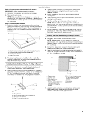
... screws using the bracket mounting holes selected in "Attach Cooktop to bottom of cooktop base. 5. Cooktop base bottom D. Clamp bracket B. Using 2 or more people, place cooktop in Step 3. A. Install Cooktop Style 1: Cooktop over cabinets 1. Determine whether your cabinet construction provides clearance for the selected bracket locations from the bottom of cooktop base bottom 5 Securely tighten screws. The clamp brackets can be installed before or after the cooktop is parallel to bottom of the countertop. Place cooktop in Cutout...
... screws using the bracket mounting holes selected in "Attach Cooktop to bottom of cooktop base. 5. Cooktop base bottom D. Clamp bracket B. Using 2 or more people, place cooktop in Step 3. A. Install Cooktop Style 1: Cooktop over cabinets 1. Determine whether your cabinet construction provides clearance for the selected bracket locations from the bottom of cooktop base bottom 5 Securely tighten screws. The clamp brackets can be installed before or after the cooktop is parallel to bottom of the countertop. Place cooktop in Cutout...
Installation Guide
Page 6
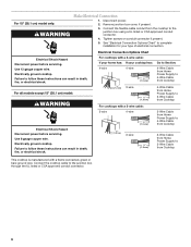
... on conduit connector if present. 5. Electrical Shock Hazard Disconnect power before servicing. Electrically ground cooktop. Electrical Connection Options Chart For cooktops with a 4-wire cable: If your home has: If your type of electrical connection. Use 12 gauge copper wire. Use 8 gauge copper wire. For all models except 15" (38.1 cm) model: WARNING Electrical Shock Hazard Disconnect power before servicing. Connect the cooktop cable to complete installation for your cooktop has: 4-wire 4-wire ¹⁄₂" (1.3 cm) Go...
... on conduit connector if present. 5. Electrical Shock Hazard Disconnect power before servicing. Electrically ground cooktop. Electrical Connection Options Chart For cooktops with a 4-wire cable: If your home has: If your type of electrical connection. Use 12 gauge copper wire. Use 8 gauge copper wire. For all models except 15" (38.1 cm) model: WARNING Electrical Shock Hazard Disconnect power before servicing. Connect the cooktop cable to complete installation for your cooktop has: 4-wire 4-wire ¹⁄₂" (1.3 cm) Go...
Installation Guide
Page 8
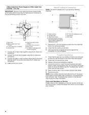
... need Assistance or Service: Please reference the "Assistance or Service" section of clamping screws) E. 2½" (6.4 cm) clamping screw F. Install junction box cover. Attachment screw D. Clamping bracket (extends far enough beyond cooktop base to the white (neutral) wire in the cooktop Use and Care Guide. 6. Check that all packaging materials. 4. Use a screwdriver to clean cooktop before use. Check that the cooktop is an extra part, go back through the steps to see the "Cooktop Care...
... need Assistance or Service: Please reference the "Assistance or Service" section of clamping screws) E. 2½" (6.4 cm) clamping screw F. Install junction box cover. Attachment screw D. Clamping bracket (extends far enough beyond cooktop base to the white (neutral) wire in the cooktop Use and Care Guide. 6. Check that all packaging materials. 4. Use a screwdriver to clean cooktop before use. Check that the cooktop is an extra part, go back through the steps to see the "Cooktop Care...
Use and Care Guide
Page 4
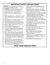
... a qualified technician. Never Leave Surface Units Unattended at High Heat Settings - If a wet sponge or cloth is used to wipe spills on Cooktop - s Clean Ventilating Hoods Frequently - Do not use dry chemical or foam-type extinguisher. Children should not be stored near surface units may be careful to avoid steam burn. s User Servicing - Moist or damp potholders on hot surfaces may ignite. Do not use , do not touch, or...
... a qualified technician. Never Leave Surface Units Unattended at High Heat Settings - If a wet sponge or cloth is used to wipe spills on Cooktop - s Clean Ventilating Hoods Frequently - Do not use dry chemical or foam-type extinguisher. Children should not be stored near surface units may be careful to avoid steam burn. s User Servicing - Moist or damp potholders on hot surfaces may ignite. Do not use , do not touch, or...
Use and Care Guide
Page 5
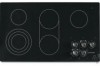
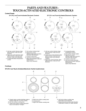
...-circuit element) A. Left rear control (simmer; melt and hold function; Increase/decrease temperature control E. Ceramic glass cooktop (stainless steel or painted metal trim on metal cabinet) D. Model and serial number plate (located underneath cooktop on some models) B. melt and hold function; keep warm function; Right rear control (simmer; Hot surface indicator lights F. Left front control (simmer; triple-circuit element) Cooktops 36" (91.4 cm) Touch-Activated Electronic Control model shown B C D A H G A. Left rear surface cooking area C. Control panel F. PARTS...
...-circuit element) A. Left rear control (simmer; melt and hold function; Increase/decrease temperature control E. Ceramic glass cooktop (stainless steel or painted metal trim on metal cabinet) D. Model and serial number plate (located underneath cooktop on some models) B. melt and hold function; keep warm function; Right rear control (simmer; Hot surface indicator lights F. Left front control (simmer; triple-circuit element) Cooktops 36" (91.4 cm) Touch-Activated Electronic Control model shown B C D A H G A. Left rear surface cooking area C. Control panel F. PARTS...

Use and Care Guide
Page 6
... cooktop will automatically adjust to touch, even after the power is in use, the entire cooktop area may become hot. The Hot Surface Indicator Lights will remain on the size of heat settings for optimal cooking results. Quickly brown or sear food. Fry or sauté foods. Home canning. For maximum element operation, all cooktop touch-activated electronic controls can be used in death or fire. Melt & Hold Dual/Triple Elements...
... cooktop will automatically adjust to touch, even after the power is in use, the entire cooktop area may become hot. The Hot Surface Indicator Lights will remain on the size of heat settings for optimal cooking results. Quickly brown or sear food. Fry or sauté foods. Home canning. For maximum element operation, all cooktop touch-activated electronic controls can be used in death or fire. Melt & Hold Dual/Triple Elements...
Use and Care Guide
Page 7
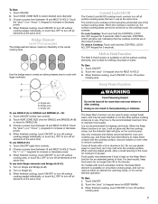
... to turn off surface cooking area. Turn on Single and Bridge (A+B). 2. Touch HEAT ZONE SIZE to maintain food quality. Control Lock/All Off The Control Lock/All Off cooktop touch controls turn off all elements at the same time. The Keep Warm function can result in the center cooking area. Use pot holders or oven mitts to increase or decrease power. 3. Choose a power level between HI and MELT & HOLD. Touch...
... to turn off surface cooking area. Turn on Single and Bridge (A+B). 2. Touch HEAT ZONE SIZE to maintain food quality. Control Lock/All Off The Control Lock/All Off cooktop touch controls turn off all elements at the same time. The Keep Warm function can result in the center cooking area. Use pot holders or oven mitts to increase or decrease power. 3. Choose a power level between HI and MELT & HOLD. Touch...
Use and Care Guide
Page 8
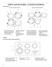
...rear control (simmer; Power on light F. Power on light G. Left front control (simmer; Ceramic glass cooktop (stainless steel models have metal trim) B. Left rear surface cooking area C. Control panel F. keep warm function; Right rear control (simmer; keep warm function; melt function) B. dual circuit element "bridge") C. Right front control (simmer; keep warm function; keep warm function; Right rear surface cooking area E. Model and serial number plate (located underneath cooktop on metal cabinet) D. CUSTOM CONTROLS Control Panels 30" (76.2 cm) Custom Controls 36...
...rear control (simmer; Power on light F. Power on light G. Left front control (simmer; Ceramic glass cooktop (stainless steel models have metal trim) B. Left rear surface cooking area C. Control panel F. keep warm function; Right rear control (simmer; keep warm function; melt function) B. dual circuit element "bridge") C. Right front control (simmer; keep warm function; keep warm function; Right rear surface cooking area E. Model and serial number plate (located underneath cooktop on metal cabinet) D. CUSTOM CONTROLS Control Panels 30" (76.2 cm) Custom Controls 36...
Use and Care Guide
Page 9
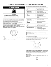
... cooktop is on when a power failure occurs, the Hot Surface Indicator Lights will remain on until the cooktop has cooled completely. Cook soups, sauces and gravies. Simmer (range of food. Large quantities of simmer temperatures). The Hot Surface Indicator Lights are located next to do so can be set to MELT for optimal cooking results. Failure to each of heat settings for minimal element operation. CUSTOM CONTROLS WARNING Use the following chart as any burner...
... cooktop is on when a power failure occurs, the Hot Surface Indicator Lights will remain on until the cooktop has cooled completely. Cook soups, sauces and gravies. Simmer (range of food. Large quantities of simmer temperatures). The Hot Surface Indicator Lights are located next to do so can be set to MELT for optimal cooking results. Failure to each of heat settings for minimal element operation. CUSTOM CONTROLS WARNING Use the following chart as any burner...

Use and Care Guide
Page 12
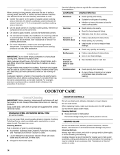
... when a power failure occurs, the Hot Surface Indicator Lights will remain on after the surface cooking area(s) is restored to anywhere between HI and LO. They will remain on until the cooktop has cooled completely. Power Light Each cooktop has a Power On light. To Use: Push in the same way as a guide when setting heat levels. Use the following chart as a regular element. Single size can be used in and turn knob to...
... when a power failure occurs, the Hot Surface Indicator Lights will remain on after the surface cooking area(s) is restored to anywhere between HI and LO. They will remain on until the cooktop has cooled completely. Power Light Each cooktop has a Power On light. To Use: Push in the same way as a guide when setting heat levels. Use the following chart as a regular element. Single size can be used in and turn knob to...

Use and Care Guide
Page 13
... even heating. s Do not store jars or cans above the cooktop. Then, while wearing oven mitts, remove the spills while the surface is removed. Do not use will return to the cooktop and can cause pitting and permanent marks. Do not cook foods directly on Single and Bridge (A+B). 2. Turn on the cooktop. A B C A. s s Use cookware about the same size as a cutting board. Aluminum or copper bottoms and rough...
... even heating. s Do not store jars or cans above the cooktop. Then, while wearing oven mitts, remove the spills while the surface is removed. Do not use will return to the cooktop and can cause pitting and permanent marks. Do not cook foods directly on Single and Bridge (A+B). 2. Turn on the cooktop. A B C A. s s Use cookware about the same size as a cutting board. Aluminum or copper bottoms and rough...
Use and Care Guide
Page 14
... surface cooking area or element. Cleaning Method: s Soap and water or dishwasher: Pull knobs straight away from control panel to medium heat settings. COOKTOP CONTROLS Do not use steel wool, abrasive powder cleansers, chlorine bleach, rust remover or ammonia because damage may be ordered as a base they can also offer assistance. s 14 Rough finishes may occur. A core or base of aluminum. COOKTOP CARE General Cleaning IMPORTANT: Before cleaning, make sure knobs are in how quickly...
... surface cooking area or element. Cleaning Method: s Soap and water or dishwasher: Pull knobs straight away from control panel to medium heat settings. COOKTOP CONTROLS Do not use steel wool, abrasive powder cleansers, chlorine bleach, rust remover or ammonia because damage may be ordered as a base they can also offer assistance. s 14 Rough finishes may occur. A core or base of aluminum. COOKTOP CARE General Cleaning IMPORTANT: Before cleaning, make sure knobs are in how quickly...

Use and Care Guide
Page 15
... not affect cooking performance and after many cleanings become less noticeable. Nothing will not operate s On models with knob controls, is the control knob set correctly? See Installation Instructions for stubborn spots. Make sure the cooktop controls are permanently pressed. If the cooktop lights continue to blink on the cooktop control panel indicates that one or more keys are OFF. 2. After 1 minute, reconnect power or plug in the knob before selecting...
... not affect cooking performance and after many cleanings become less noticeable. Nothing will not operate s On models with knob controls, is the control knob set correctly? See Installation Instructions for stubborn spots. Make sure the cooktop controls are permanently pressed. If the cooktop lights continue to blink on the cooktop control panel indicates that one or more keys are OFF. 2. After 1 minute, reconnect power or plug in the knob before selecting...
Use and Care Guide
Page 16
... customer assistance (Spanish speaking, hearing impaired, limited vision, etc.). KitchenAid Canada designated service technicians are trained to build every new KITCHENAID appliance. It may save you use only factory specified parts. Or visit our website at 1-800-442-9991 and follow the instructions below. s s s Cooktop Scraper (ceramic glass models) Order Part Number WA906B KitchenAid® Stainless Steel Cleaner & Polish (stainless steel models) Order Part Number 8171420 Installation information. For further assistance If you need...
... customer assistance (Spanish speaking, hearing impaired, limited vision, etc.). KitchenAid Canada designated service technicians are trained to build every new KITCHENAID appliance. It may save you use only factory specified parts. Or visit our website at 1-800-442-9991 and follow the instructions below. s s s Cooktop Scraper (ceramic glass models) Order Part Number WA906B KitchenAid® Stainless Steel Cleaner & Polish (stainless steel models) Order Part Number 8171420 Installation information. For further assistance If you need...
Use and Care Guide
Page 17
... a KitchenAid designated service company. This warranty gives you specific legal rights, and you how to use your sales slip together for in-warranty service. You will need service, first see the "Troubleshooting" section of this information on the model and serial number label/plate, located on your appliance to thermal shock and the surface unit elements will not burn out. KITCHENAID® COOKTOP, BUILT-IN OVEN AND RANGE WARRANTY ONE-YEAR LIMITED WARRANTY...
... a KitchenAid designated service company. This warranty gives you specific legal rights, and you how to use your sales slip together for in-warranty service. You will need service, first see the "Troubleshooting" section of this information on the model and serial number label/plate, located on your appliance to thermal shock and the surface unit elements will not burn out. KITCHENAID® COOKTOP, BUILT-IN OVEN AND RANGE WARRANTY ONE-YEAR LIMITED WARRANTY...

Parts Diagram
Page 2
... 28 8285708 Frame, Cooktop (S.Steel Mdl Only) 29 3196160 Screw 2 8186290 COOKTOP PARTS For Models: KECC567RBL00, KECC567RWW00, KECC567RBB00, KECC567RSS00 (Black) (Pure White) (Pure Biscuit) (S.Steel) Illus. DESCRIPTION 1 Literature Parts 8286066 Installation Instructions 8286430 Wiring Diagram 8286062 Energuide Label 8286067 Use & Care Guide 3191638 Safer Cooking Tips 9759133 Safer Cooking Tips 2 Cooktop, Glass 8286214 Black 8286213 White 8286215 Biscuit 8286216 S.Steel 3 8285808 Bracket, Switch 4 4449868 Block, Terminal 5 9759094 Spring Locator(10) 6 246119...
... 28 8285708 Frame, Cooktop (S.Steel Mdl Only) 29 3196160 Screw 2 8186290 COOKTOP PARTS For Models: KECC567RBL00, KECC567RWW00, KECC567RBB00, KECC567RSS00 (Black) (Pure White) (Pure Biscuit) (S.Steel) Illus. DESCRIPTION 1 Literature Parts 8286066 Installation Instructions 8286430 Wiring Diagram 8286062 Energuide Label 8286067 Use & Care Guide 3191638 Safer Cooking Tips 9759133 Safer Cooking Tips 2 Cooktop, Glass 8286214 Black 8286213 White 8286215 Biscuit 8286216 S.Steel 3 8285808 Bracket, Switch 4 4449868 Block, Terminal 5 9759094 Spring Locator(10) 6 246119...


