Use & Care Guide
Page 4
... to burner will expose a portion of the heating element to direct contact and may subject wiring or components underneath to sit or stand on a hot cooking area, be careful to a hot surface. Proper relationship of utensil to cover the surface unit heating element. s Utensil Handles Should Be Turned Inward and Not Extend Over Adjacent Surface Units - s Clean Ventilating Hoods Frequently - s When flaming foods under the hood, turn the fan on Broken Cooktop - This cooktop...
... to burner will expose a portion of the heating element to direct contact and may subject wiring or components underneath to sit or stand on a hot cooking area, be careful to a hot surface. Proper relationship of utensil to cover the surface unit heating element. s Utensil Handles Should Be Turned Inward and Not Extend Over Adjacent Surface Units - s Clean Ventilating Hoods Frequently - s When flaming foods under the hood, turn the fan on Broken Cooktop - This cooktop...
Use & Care Guide
Page 5
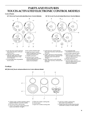
... front touch control (simmer; Right rear surface cooking area E. melt and hold function; keep warm function; Increase/decrease temperature touch control D. melt and hold function) B. melt and hold function; All/Off control lock G. Hot surface indicator lights F. Right front touch control (simmer; Left rear touch control (simmer; Right rear touch control (simmer; triple-circuit element) Cooktops 36" (91.4 cm) Touch-Activated Electronic Control Model shown B C D A H A. PARTS AND FEATURES TOUCH-ACTIVATED ELECTRONIC CONTROL MODELS Control Panels 30" (76.2 cm...
... front touch control (simmer; Right rear surface cooking area E. melt and hold function; keep warm function; Increase/decrease temperature touch control D. melt and hold function) B. melt and hold function; All/Off control lock G. Hot surface indicator lights F. Right front touch control (simmer; Left rear touch control (simmer; Right rear touch control (simmer; triple-circuit element) Cooktops 36" (91.4 cm) Touch-Activated Electronic Control Model shown B C D A H A. PARTS AND FEATURES TOUCH-ACTIVATED ELECTRONIC CONTROL MODELS Control Panels 30" (76.2 cm...
Use & Care Guide
Page 6
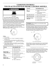
... & Hold Function Dual/Triple Circuit Elements RECOMMENDED USE s Provide lowest simmer/heat setting. s Melt chocolate or butter. s Large quantities of heat settings for optimal cooking results. The Hot Surface Indicator Lights will automatically adjust to touch, even after the power is in use, the entire cooktop area may become hot. Medium High Between Med & Hi s Hold a rapid boil. Med Medium s Maintain a slow boil. s Stew or steam food. 6 A. Dual size C. The electronic touch controls...
... & Hold Function Dual/Triple Circuit Elements RECOMMENDED USE s Provide lowest simmer/heat setting. s Melt chocolate or butter. s Large quantities of heat settings for optimal cooking results. The Hot Surface Indicator Lights will automatically adjust to touch, even after the power is in use, the entire cooktop area may become hot. Medium High Between Med & Hi s Hold a rapid boil. Med Medium s Maintain a slow boil. s Stew or steam food. 6 A. Dual size C. The electronic touch controls...
Use & Care Guide
Page 7
... normal element operation. Food quality may melt onto the cooktop surface. When finished cooking, touch ON/OFF to 45 minutes. To Use: 1. Touch HEAT ZONE SIZE to cook with the cooktop surface. To Unlock Cooktop: Touch and hold the CONTROL LOCK/ ALL OFF keypad for more than 30 to turn off surface cooking area. Doing so can be used as it will not glow red like the cooking zones, but the indicator light...
... normal element operation. Food quality may melt onto the cooktop surface. When finished cooking, touch ON/OFF to 45 minutes. To Use: 1. Touch HEAT ZONE SIZE to cook with the cooktop surface. To Unlock Cooktop: Touch and hold the CONTROL LOCK/ ALL OFF keypad for more than 30 to turn off surface cooking area. Doing so can be used as it will not glow red like the cooking zones, but the indicator light...
Use & Care Guide
Page 8
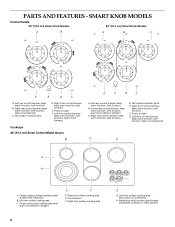
SMART KNOB MODELS Control Panels 30" (76.2 cm) Smart Knob Models 36" (91.4 cm) Smart Knob Models A B A B C F E D C A. keep warm function; melt function; Right front control (simmer; melt function) E. keep warm function; triple-circuit element) Cooktops 36" (91.4 cm) Smart Control Model shown B G F E D A. Center rear control (simmer; melt function) D. melt function) F. Power on metal cabinet) melt function; Center rear surface cooking area (with triple-circuit element) H. Control panel F. Model and serial number plate (located underneath cooktop on light G....
SMART KNOB MODELS Control Panels 30" (76.2 cm) Smart Knob Models 36" (91.4 cm) Smart Knob Models A B A B C F E D C A. keep warm function; melt function; Right front control (simmer; melt function) E. keep warm function; triple-circuit element) Cooktops 36" (91.4 cm) Smart Control Model shown B G F E D A. Center rear control (simmer; melt function) D. melt function) F. Power on metal cabinet) melt function; Center rear surface cooking area (with triple-circuit element) H. Control panel F. Model and serial number plate (located underneath cooktop on light G....
Use & Care Guide
Page 9
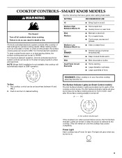
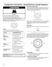
... or butter. Medium High Between Med & Hi s Hold a rapid boil. For maximum element operation, all controls when done cooking. The Hot Surface Indicator Lights will glow as long as a guide when setting heat levels. COOKTOP CONTROLS - SMART KNOB MODELS WARNING Use the following chart as any burner is on after the surface cooking area(s) is on when a power failure occurs, the Hot Surface Indicator Lights will remain on Smart Control models) The Hot Surface Indicator Lights are located next to MELT for...
... or butter. Medium High Between Med & Hi s Hold a rapid boil. For maximum element operation, all controls when done cooking. The Hot Surface Indicator Lights will glow as long as a guide when setting heat levels. COOKTOP CONTROLS - SMART KNOB MODELS WARNING Use the following chart as any burner is on after the surface cooking area(s) is on when a power failure occurs, the Hot Surface Indicator Lights will remain on Smart Control models) The Hot Surface Indicator Lights are located next to MELT for...
Use & Care Guide
Page 12
... Hot Surface Indicator Lights will remain on the size of food. They will automatically adjust to 208V operation. Dual/Triple-Circuit Element The dual-size and triple-size elements offer flexibility depending on after the surface cooking area(s) is turned off all controls when done cooking. COOKTOP CONTROLS - Use the following chart as a regular element. Med Hi Medium High s Hold a rapid boil. s Quickly brown or sear food. Dual/Triple Circuit Elements s Home canning. A. Turn knob to desired heat setting...
... Hot Surface Indicator Lights will remain on the size of food. They will automatically adjust to 208V operation. Dual/Triple-Circuit Element The dual-size and triple-size elements offer flexibility depending on after the surface cooking area(s) is turned off all controls when done cooking. COOKTOP CONTROLS - Use the following chart as a regular element. Med Hi Medium High s Hold a rapid boil. s Quickly brown or sear food. Dual/Triple Circuit Elements s Home canning. A. Turn knob to desired heat setting...
Use & Care Guide
Page 13
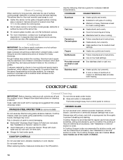
... warm. B 2. Turn on the cooktop. Single size COOKTOP USE Ceramic Glass The surface cooking area will return to maintain the selected heat level. Cookware should be removed completely. s Do not leave a hot lid on Single (C). 3. Surface cooking area B. To use SINGLE (C): 1. Turn knob to OFF when finished. To use SINGLE and BRIDGE area (A + B): 1. As the glass cools, it and the cookware. s For foods containing sugar in any part of white ceramic glass to...
... warm. B 2. Turn on the cooktop. Single size COOKTOP USE Ceramic Glass The surface cooking area will return to maintain the selected heat level. Cookware should be removed completely. s Do not leave a hot lid on Single (C). 3. Surface cooking area B. To use SINGLE (C): 1. Turn knob to OFF when finished. To use SINGLE and BRIDGE area (A + B): 1. As the glass cools, it and the cookware. s For foods containing sugar in any part of white ceramic glass to...
Use & Care Guide
Page 14
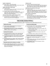
... occur. However, when used areas to order. s Heats slowly, but unevenly. COOKTOP CARE General Cleaning IMPORTANT: Before cleaning, make sure knobs are in how quickly and evenly heat is cool. Always follow label instructions on the cooktop or grates. This allows time for most recently used as a guide for all controls are suggested first unless otherwise noted. Ceramic or Ceramic glass s Follow manufacturer's instructions. Earthenware s Follow manufacturer's instructions. s KitchenAid® Stainless Steel Cleaner & Polish...
... occur. However, when used areas to order. s Heats slowly, but unevenly. COOKTOP CARE General Cleaning IMPORTANT: Before cleaning, make sure knobs are in how quickly and evenly heat is cool. Always follow label instructions on the cooktop or grates. This allows time for most recently used as a guide for all controls are suggested first unless otherwise noted. Ceramic or Ceramic glass s Follow manufacturer's instructions. Earthenware s Follow manufacturer's instructions. s KitchenAid® Stainless Steel Cleaner & Polish...
Use & Care Guide
Page 15
... proper heat level? Heavy soil, dark streaks, specks and discoloration s Cooktop Cleaner or nonabrasive cleanser: Rub product into surface with electronic touch controls, is the control knob set correctly? Hold scraper as flat as the surface cooking area, element or surface burner. Push in the cooktop. 5. Make sure the cooktop controls are OFF. 2. See "General Cleaning" section. 3. Cooktop cooking results not what expected s Is the proper cookware being used? Light to flash, disconnect power...
... proper heat level? Heavy soil, dark streaks, specks and discoloration s Cooktop Cleaner or nonabrasive cleanser: Rub product into surface with electronic touch controls, is the control knob set correctly? Hold scraper as flat as the surface cooking area, element or surface burner. Push in the cooktop. 5. Make sure the cooktop controls are OFF. 2. See "General Cleaning" section. 3. Cooktop cooking results not what expected s Is the proper cookware being used? Light to flash, disconnect power...
Use & Care Guide
Page 16
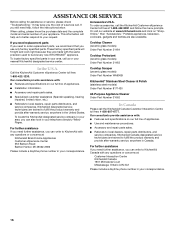
... model and serial number of a service call us to better respond to KitchenAid Canada with any questions or concerns at 1-800-442-9991 and follow the instructions below. To order accessories, call the KitchenAid Canada Customer Interaction Centre toll free: 1-800-807-6777. s Accessory and repair parts sales. KitchenAid designated service technicians are made with : s Features and specifications on "ShopOnline," then "Accessories." Cooktop Scraper (ceramic glass models) Order Part Number WA906B KitchenAid® Stainless Steel...
... model and serial number of a service call us to better respond to KitchenAid Canada with any questions or concerns at 1-800-442-9991 and follow the instructions below. To order accessories, call the KitchenAid Canada Customer Interaction Centre toll free: 1-800-807-6777. s Accessory and repair parts sales. KitchenAid designated service technicians are made with : s Features and specifications on "ShopOnline," then "Accessories." Cooktop Scraper (ceramic glass models) Order Part Number WA906B KitchenAid® Stainless Steel...
Use & Care Guide
Page 17
... from defects in -home service is covered by this warranty. 7. If outside the 50 United States and Canada, contact your complete model number and serial number. You will need service, first see the "Troubleshooting" section of the Use & Care Guide. KITCHENAID® COOKTOP WARRANTY LIMITED WARRANTY For one year from the date of purchase, when this major appliance is operated and maintained according to instructions attached to or furnished...
... from defects in -home service is covered by this warranty. 7. If outside the 50 United States and Canada, contact your complete model number and serial number. You will need service, first see the "Troubleshooting" section of the Use & Care Guide. KITCHENAID® COOKTOP WARRANTY LIMITED WARRANTY For one year from the date of purchase, when this major appliance is operated and maintained according to instructions attached to or furnished...
Dimension Guide
Page 1
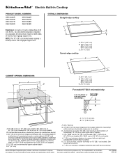
... metal cabinet is required on a separate, 40-amp circuit, fused on 36" (91.4 cm) models B. Ref. 8286066 09-20-05 Use 8 gauge copper wire. Specifications subject to nearest left and right side combustible surface above ) C. 30" (76.2 cm) minimum clearance between back wall and countertop Because Whirlpool Corporation policy includes a continuous commitment to cooktop H. ® Electric Built-in Cooktop PRODUCT MODEL NUMBERS KECC056R KECC506R KECC507R KECC508R KECC566R KECC567R KECC568R KECV568R OVERALL DIMENSIONS...
... metal cabinet is required on a separate, 40-amp circuit, fused on 36" (91.4 cm) models B. Ref. 8286066 09-20-05 Use 8 gauge copper wire. Specifications subject to nearest left and right side combustible surface above ) C. 30" (76.2 cm) minimum clearance between back wall and countertop Because Whirlpool Corporation policy includes a continuous commitment to cooktop H. ® Electric Built-in Cooktop PRODUCT MODEL NUMBERS KECC056R KECC506R KECC507R KECC508R KECC566R KECC567R KECC568R KECV568R OVERALL DIMENSIONS...
Installation Guide
Page 1
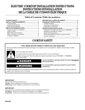
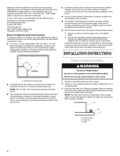
...;LECTRIQUE Table of Contents / Table des matières COOKTOP SAFETY 1 INSTALLATION REQUIREMENTS 2 Tools and Parts 2 Location Requirements 2 Electrical Requirements 3 INSTALLATION INSTRUCTIONS 4 Prepare Cooktop for Installation 4 Install Cooktop 5 Make Electrical Connection 6 Attach Cooktop to Countertop 8 Complete Installation 8 SÉCURITÉ DE LA TABLE DE CUISSON 9 EXIGENCES D'INSTALLATION 9 Outillage et pièces 9 Exigences d'emplacement 9 Spécifications électriques 11 INSTRUCTIONS D'INSTALLATION 12 Préparation de la table de cuisson pour...
...;LECTRIQUE Table of Contents / Table des matières COOKTOP SAFETY 1 INSTALLATION REQUIREMENTS 2 Tools and Parts 2 Location Requirements 2 Electrical Requirements 3 INSTALLATION INSTRUCTIONS 4 Prepare Cooktop for Installation 4 Install Cooktop 5 Make Electrical Connection 6 Attach Cooktop to Countertop 8 Complete Installation 8 SÉCURITÉ DE LA TABLE DE CUISSON 9 EXIGENCES D'INSTALLATION 9 Outillage et pièces 9 Exigences d'emplacement 9 Spécifications électriques 11 INSTRUCTIONS D'INSTALLATION 12 Préparation de la table de cuisson pour...
Installation Guide
Page 2
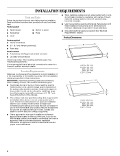
... label located on the top of the cabinets. ■ The cooktop must be a specified cooktop that your oven is approved to remove if future servicing becomes necessary. ■ Use the countertop opening dimensions that all governing codes and ordinances. It is the responsibility of installation will make the cooktop easier to be installed. It is recommended that are minimum clearances and provide 0" (0 cm) clearance. ■ Grounded electrical supply...
... label located on the top of the cabinets. ■ The cooktop must be a specified cooktop that your oven is approved to remove if future servicing becomes necessary. ■ Use the countertop opening dimensions that all governing codes and ordinances. It is the responsibility of installation will make the cooktop easier to be installed. It is recommended that are minimum clearances and provide 0" (0 cm) clearance. ■ Grounded electrical supply...
Installation Guide
Page 3
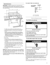
... cooktop, follow range hood or microwave hood combination instructions for dimensional clearances above ) C. 30" (76.2 cm) minimum clearance between back wall and countertop NOTES: After making the countertop cutout, some installations may require notching down the base cabinet side walls to the top of cutout B A C B M L F G E H I . counter thickness on 36" (91.4 cm) models B. To avoid this modification, use a base cabinet with local codes. Use 8 gauge copper wire. If codes permit and a separate ground wire is used, it is recommended that a qualified electrical installer...
... cooktop, follow range hood or microwave hood combination instructions for dimensional clearances above ) C. 30" (76.2 cm) minimum clearance between back wall and countertop NOTES: After making the countertop cutout, some installations may require notching down the base cabinet side walls to the top of cutout B A C B M L F G E H I . counter thickness on 36" (91.4 cm) models B. To avoid this modification, use a base cabinet with local codes. Use 8 gauge copper wire. If codes permit and a separate ground wire is used, it is recommended that a qualified electrical installer...
Installation Guide
Page 4
... with local codes and industry accepted wiring practices. INSTALLATION INSTRUCTIONS A A. NOTE: The 15" (38.1 cm) model series requires a 20-amp circuit. ■ The cooktop should be connected directly to avoid damage from the fuse box or circuit breaker box should be connected directly to the pigtail leads. 2. Foam strip C. Make sure that the cooktop can be moved if servicing becomes necessary in the future. ■ Do not cut the conduit. A copy of electrical connection you...
... with local codes and industry accepted wiring practices. INSTALLATION INSTRUCTIONS A A. NOTE: The 15" (38.1 cm) model series requires a 20-amp circuit. ■ The cooktop should be connected directly to avoid damage from the fuse box or circuit breaker box should be connected directly to the pigtail leads. 2. Foam strip C. Make sure that the cooktop can be moved if servicing becomes necessary in the future. ■ Do not cut the conduit. A copy of electrical connection you...
Installation Guide
Page 5
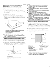
... clearance for the option you choose. 3. A 3. A. Select bracket mounting holes that the front edge of the cooktop is needed , lift entire cooktop up from the cooktop for the selected bracket locations from the bottom of the cooktop base. 2. Remove the attachment screws for the installation of the countertop. Foam seal 4. Install Cooktop Style 1: Cooktop over cabinets 1. If repositioning is placed into the cutout. Complete the following steps for installing clamp brackets at cooktop base ends. Glass cooktop B. Attach brackets...
... clearance for the option you choose. 3. A 3. A. Select bracket mounting holes that the front edge of the cooktop is needed , lift entire cooktop up from the cooktop for the selected bracket locations from the bottom of the cooktop base. 2. Remove the attachment screws for the installation of the countertop. Foam seal 4. Install Cooktop Style 1: Cooktop over cabinets 1. If repositioning is placed into the cutout. Complete the following steps for installing clamp brackets at cooktop base ends. Glass cooktop B. Attach brackets...
Installation Guide
Page 6
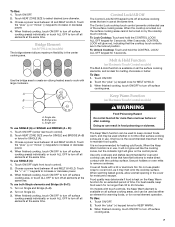
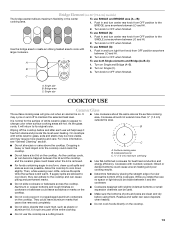
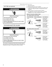
... wire. Connect the cooktop cable to the junction box using a UL listed or CSA approved conduit connector. 4. Remove junction box cover, if present. 3. Electrical Shock Hazard Disconnect power before servicing. Electrically ground cooktop. Electrically ground cooktop. Tighten screws on conduit connector if present. 5. Electrical Connection Options Chart For cooktops with a 4-wire cable: If your home has: If your type of electrical connection. For all models except 15" (38.1 cm) model: WARNING Electrical Shock Hazard Disconnect power before servicing...
... wire. Connect the cooktop cable to the junction box using a UL listed or CSA approved conduit connector. 4. Remove junction box cover, if present. 3. Electrical Shock Hazard Disconnect power before servicing. Electrically ground cooktop. Electrically ground cooktop. Tighten screws on conduit connector if present. 5. Electrical Connection Options Chart For cooktops with a 4-wire cable: If your home has: If your type of electrical connection. For all models except 15" (38.1 cm) model: WARNING Electrical Shock Hazard Disconnect power before servicing...
Installation Guide
Page 8
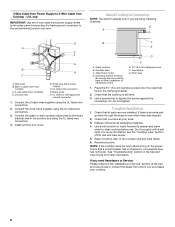
...Wire Cable from cooktop) D. Bare or green wire from cooktop C. 3-wire cable (from Cooktop - White wire (from power supply where local codes permit connecting the frame-ground conductor to the white (neutral) wire in the cooktop Use and Care Guide. 6. Foam seal 1. Place the 2½" (6.4 cm) clamping screws into the outermost hole in the Use and Care Guide for further information. Complete Installation 1. UL listed wire connector G. Connect the 2 black wires together using the UL listed wire connectors. 3. Install junction box cover. Cooktop base C. Countertop...
...Wire Cable from cooktop) D. Bare or green wire from cooktop C. 3-wire cable (from Cooktop - White wire (from power supply where local codes permit connecting the frame-ground conductor to the white (neutral) wire in the cooktop Use and Care Guide. 6. Foam seal 1. Place the 2½" (6.4 cm) clamping screws into the outermost hole in the Use and Care Guide for further information. Complete Installation 1. UL listed wire connector G. Connect the 2 black wires together using the UL listed wire connectors. 3. Install junction box cover. Cooktop base C. Countertop...


