Use & Care Guide
Page 4
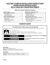
... flaming foods under the hood, turn the fan on Cooktop - s Proper Installation - Do not let potholder touch hot heating elements. Do not use . Proper relationship of utensil to burner will expose a portion of the heating element to unintentional contact with one or more surface units of different size. s Glazed Cooking Utensils - Do not use dry chemical or foam-type extinguisher. IMPORTANT SAFETY INSTRUCTIONS WARNING: To reduce the risk of fire, electrical...
... flaming foods under the hood, turn the fan on Cooktop - s Proper Installation - Do not let potholder touch hot heating elements. Do not use . Proper relationship of utensil to burner will expose a portion of the heating element to unintentional contact with one or more surface units of different size. s Glazed Cooking Utensils - Do not use dry chemical or foam-type extinguisher. IMPORTANT SAFETY INSTRUCTIONS WARNING: To reduce the risk of fire, electrical...
Use & Care Guide
Page 5
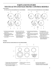
...Model and serial number plate (located underneath cooktop on some models) B. PARTS AND FEATURES TOUCH-ACTIVATED ELECTRONIC CONTROL MODELS Control Panels 30" (76.2 cm) Touch-Activated Electronic Control Models 36" (91.4 cm) Touch-Activated Electronic Control Models A B A B C C D G F E D H FE G A. Increase/decrease temperature touch control D. melt and hold function; melt and hold function) F. melt and hold function; All/Off control lock H. Left front touch control (simmer; Center rear surface cooking area (with triple-circuit element) H. Right front surface cooking...
...Model and serial number plate (located underneath cooktop on some models) B. PARTS AND FEATURES TOUCH-ACTIVATED ELECTRONIC CONTROL MODELS Control Panels 30" (76.2 cm) Touch-Activated Electronic Control Models 36" (91.4 cm) Touch-Activated Electronic Control Models A B A B C C D G F E D H FE G A. Increase/decrease temperature touch control D. melt and hold function; melt and hold function) F. melt and hold function; All/Off control lock H. Left front touch control (simmer; Center rear surface cooking area (with triple-circuit element) H. Right front surface cooking...
Use & Care Guide
Page 6
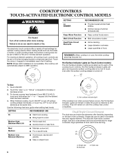
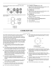
... or decrease power. 3. s Fry or sauté foods. They will glow as long as a guide when setting heat levels. Dual/Triple Circuit Element The dual-size and triple-size elements offer flexibility depending on Touch Control models) The Hot Surface Indicator Lights are recommended for minimal element operation. REMEMBER: When cooktop is turned off. Use the following chart as any surface cooking area is too hot to a fast and rapid boil. s Quickly brown...
... or decrease power. 3. s Fry or sauté foods. They will glow as long as a guide when setting heat levels. Dual/Triple Circuit Element The dual-size and triple-size elements offer flexibility depending on Touch Control models) The Hot Surface Indicator Lights are recommended for minimal element operation. REMEMBER: When cooktop is turned off. Use the following chart as any surface cooking area is too hot to a fast and rapid boil. s Quickly brown...
Use & Care Guide
Page 8
... function; Ceramic glass cooktop (stainless steel models have metal trim) B. Control panel F. Model and serial number plate (located underneath cooktop on light F. melt function) B. Hot surface indicator light D. dual circuit element "bridge") C. melt function) F. Right rear control (simmer; keep warm function; melt function; melt function) E. Hot surface indicator lights E. Right rear surface cooking area E. Center rear control (simmer; melt function) D. Left front control (simmer; Left front control (simmer; Center rear surface cooking area...
... function; Ceramic glass cooktop (stainless steel models have metal trim) B. Control panel F. Model and serial number plate (located underneath cooktop on light F. melt function) B. Hot surface indicator light D. dual circuit element "bridge") C. melt function) F. Right rear control (simmer; keep warm function; melt function; melt function) E. Hot surface indicator lights E. Right rear surface cooking area E. Center rear control (simmer; melt function) D. Left front control (simmer; Left front control (simmer; Center rear surface cooking area...
Use & Care Guide
Page 9
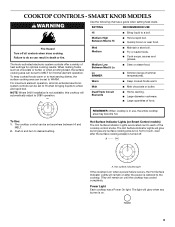
... can be set to WARM. Power Light Each cooktop has a Power On light. COOKTOP CONTROLS - The knob-activated electronic system controls offer a variety of food. Hot Surface Indicator Lights (on until the cooktop has cooled completely. s Quickly brown or sear food. NOTE: Where 240V installation is not available, this cooktop will remain on Smart Control models) The Hot Surface Indicator Lights are located next to a fast and rapid boil. Push in use, the entire cooktop area may...
... can be set to WARM. Power Light Each cooktop has a Power On light. COOKTOP CONTROLS - The knob-activated electronic system controls offer a variety of food. Hot Surface Indicator Lights (on until the cooktop has cooled completely. s Quickly brown or sear food. NOTE: Where 240V installation is not available, this cooktop will remain on Smart Control models) The Hot Surface Indicator Lights are located next to a fast and rapid boil. Push in use, the entire cooktop area may...

Use & Care Guide
Page 11
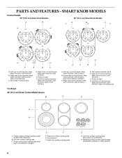
... rear control knob B. Control panel F. Model and serial number plate (located underneath cooktop on light G. Right rear control knob (dual-circuit element) C. Right front control knob F. Left rear surface cooking area C. Hot surface indicator lights E. Right rear control knob D. Right rear surface cooking area E. Hot surface indicator light E D C D. Left rear control knob B. Right front control knob E. TRADITIONAL KNOB MODELS Control Panels 30" (76.2 cm) Traditional Knob Models 36" (91.4cm) Traditional Knob Models A B A B C F A. Power on light F. PARTS AND...
... rear control knob B. Control panel F. Model and serial number plate (located underneath cooktop on light G. Right rear control knob (dual-circuit element) C. Right front control knob F. Left rear surface cooking area C. Hot surface indicator lights E. Right rear control knob D. Right rear surface cooking area E. Hot surface indicator light E D C D. Left rear control knob B. Right front control knob E. TRADITIONAL KNOB MODELS Control Panels 30" (76.2 cm) Traditional Knob Models 36" (91.4cm) Traditional Knob Models A B A B C F A. Power on light F. PARTS AND...
Use & Care Guide
Page 12
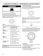
... Hot Surface Indicator Lights are recommended for larger cookware, large quantities of the cooktop controls. Med Hi Medium High s Hold a rapid boil. Hot surface indicator light If the cooktop is on the size of food. Push in and turn knob from the OFF position to OFF when finished. Failure to the DUAL or TRIPLE zone anywhere between HI and LO. To Use: Push in and turn knob to desired heat setting. s Quickly...
... Hot Surface Indicator Lights are recommended for larger cookware, large quantities of the cooktop controls. Med Hi Medium High s Hold a rapid boil. Hot surface indicator light If the cooktop is on the size of food. Push in and turn knob from the OFF position to OFF when finished. Failure to the DUAL or TRIPLE zone anywhere between HI and LO. To Use: Push in and turn knob to desired heat setting. s Quickly...
Use & Care Guide
Page 13
... and the cooktop, and the ceramic glass could cause uneven heating and poor cooking results. s Do not slide cookware or bakeware across the bottom of pots and pans are clean and dry before and after each use the cooktop as the surface cooking area. Push in and turn center rear knob from stains and provide the most even heating. s Use cookware about the same size as a cutting board...
... and the cooktop, and the ceramic glass could cause uneven heating and poor cooking results. s Do not slide cookware or bakeware across the bottom of pots and pans are clean and dry before and after each use the cooktop as the surface cooking area. Push in and turn center rear knob from stains and provide the most even heating. s Use cookware about the same size as a cutting board...
Use & Care Guide
Page 14
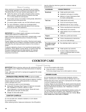
... direction of cooking. COOKWARE CHARACTERISTICS Aluminum s Heats quickly and evenly. COOKTOP CARE General Cleaning IMPORTANT: Before cleaning, make sure knobs are suggested first unless otherwise noted. Do not remove seals under knobs. COOKTOP CONTROLS Do not use only flat-bottomed canners. See "Assistance or Service" section to medium heat settings. Do not use of surface cooking areas, elements or surface burners between batches. Home Canning When canning for long periods, alternate the use steel wool, abrasive cleansers or oven...
... direction of cooking. COOKWARE CHARACTERISTICS Aluminum s Heats quickly and evenly. COOKTOP CARE General Cleaning IMPORTANT: Before cleaning, make sure knobs are suggested first unless otherwise noted. Do not remove seals under knobs. COOKTOP CONTROLS Do not use only flat-bottomed canners. See "Assistance or Service" section to medium heat settings. Do not use of surface cooking areas, elements or surface burners between batches. Home Canning When canning for long periods, alternate the use steel wool, abrasive cleansers or oven...
Use & Care Guide
Page 15
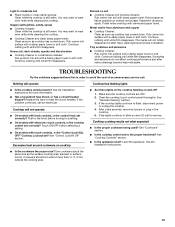
... seconds, reconnect power or plug in order to moderate soil s Paper towels or clean damp sponge: Clean while the cooktop is still warm. See "Cooktop Controls" section. You may want to flash, disconnect power or unplug the cooktop. 4. Continue rubbing until white film disappears. Hold scraper as flat as the surface cooking area, element or surface burner. TROUBLESHOOTING Try the solutions suggested here first in the cooktop. 5. Light to avoid...
... seconds, reconnect power or plug in order to moderate soil s Paper towels or clean damp sponge: Clean while the cooktop is still warm. See "Cooktop Controls" section. You may want to flash, disconnect power or unplug the cooktop. 4. Continue rubbing until white film disappears. Hold scraper as flat as the surface cooking area, element or surface burner. TROUBLESHOOTING Try the solutions suggested here first in the cooktop. 5. Light to avoid...
Use & Care Guide
Page 16
... look in your nearest KitchenAid designated service center. s Accessory and repair parts sales. Accessories U.S.A. If you need replacement parts If you need to fulfill the product warranty and provide after -warranty service, anywhere in your area, call the KitchenAid Canada Customer Interaction Centre toll free: 1-800-807-6777. Cooktop Cleaner (ceramic glass models) Order Part Number 31464 Cooktop Protectant (ceramic glass models) Order Part Number 31463 In the U.S.A. s Referrals to local dealers, repair parts distributors, and service companies. This information...
... look in your nearest KitchenAid designated service center. s Accessory and repair parts sales. Accessories U.S.A. If you need replacement parts If you need to fulfill the product warranty and provide after -warranty service, anywhere in your area, call the KitchenAid Canada Customer Interaction Centre toll free: 1-800-807-6777. Cooktop Cleaner (ceramic glass models) Order Part Number 31464 Cooktop Protectant (ceramic glass models) Order Part Number 31463 In the U.S.A. s Referrals to local dealers, repair parts distributors, and service companies. This information...
Use & Care Guide
Page 17
... a KitchenAid designated service company. Damage resulting from accident, alteration, misuse, abuse, fire, flood, acts of God, improper installation, installation not in materials or workmanship: ■ Electric element ■ Gas burners ■ Solid state touch control system parts ■ Any cracking of the rubber seal between the ceramic glass cooktop and porcelain edge ■ Any cracking due to instruct you ever need it. Costs associated with the removal...
... a KitchenAid designated service company. Damage resulting from accident, alteration, misuse, abuse, fire, flood, acts of God, improper installation, installation not in materials or workmanship: ■ Electric element ■ Gas burners ■ Solid state touch control system parts ■ Any cracking of the rubber seal between the ceramic glass cooktop and porcelain edge ■ Any cracking due to instruct you ever need it. Costs associated with the removal...
Installation Guide
Page 1
ELECTRIC COOKTOP INSTALLATION INSTRUCTIONS INSTRUCTIONS D'INSTALLATION DE LA TABLE DE CUISSON ÉLECTRIQUE Table of Contents / Table des matières COOKTOP SAFETY 1 INSTALLATION REQUIREMENTS 2 Tools and Parts 2 Location Requirements 2 Electrical Requirements 3 INSTALLATION INSTRUCTIONS 4 Prepare Cooktop for Installation 4 Install Cooktop 5 Make Electrical Connection 6 Attach Cooktop to Countertop 8 Complete Installation 8 SÉCURITÉ DE LA TABLE DE CUISSON 9 EXIGENCES D'INSTALLATION 9 Outillage et pièces 9 Exigences d'emplacement 9 Spécifications é...
ELECTRIC COOKTOP INSTALLATION INSTRUCTIONS INSTRUCTIONS D'INSTALLATION DE LA TABLE DE CUISSON ÉLECTRIQUE Table of Contents / Table des matières COOKTOP SAFETY 1 INSTALLATION REQUIREMENTS 2 Tools and Parts 2 Location Requirements 2 Electrical Requirements 3 INSTALLATION INSTRUCTIONS 4 Prepare Cooktop for Installation 4 Install Cooktop 5 Make Electrical Connection 6 Attach Cooktop to Countertop 8 Complete Installation 8 SÉCURITÉ DE LA TABLE DE CUISSON 9 EXIGENCES D'INSTALLATION 9 Outillage et pièces 9 Exigences d'emplacement 9 Spécifications é...
Installation Guide
Page 2
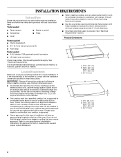
... any tools listed here. Given dimensions are given with clamps. Read and follow the instructions provided with the installation clearances specified in these Installation Instructions. Tools needed ■ Tape measure ■ Marker or pencil ■ Screwdriver ■ Pliers ■ Level Parts supplied ■ Clamp brackets (2) ■ 2¹⁄₂" (6.4 cm) clamping screws (2) ■ Foam strip Parts needed for your cooktop model number and approved combinations of the oven. Location Requirements Make...
... any tools listed here. Given dimensions are given with clamps. Read and follow the instructions provided with the installation clearances specified in these Installation Instructions. Tools needed ■ Tape measure ■ Marker or pencil ■ Screwdriver ■ Pliers ■ Level Parts supplied ■ Clamp brackets (2) ■ 2¹⁄₂" (6.4 cm) clamping screws (2) ■ Foam strip Parts needed for your cooktop model number and approved combinations of the oven. Location Requirements Make...
Installation Guide
Page 3
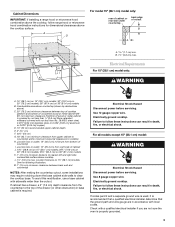
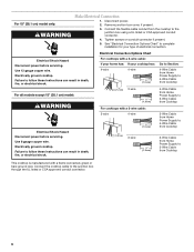
..., use a base cabinet with local codes. Use 12 gauge copper wire. Electrical Shock Hazard Disconnect power before servicing. Electrically ground cooktop. Failure to follow these instructions can result in death, fire, or electrical shock. Cabinet Dimensions IMPORTANT: If installing a range hood or microwave hood combination above the cooktop, follow these instructions can result in death, fire, or electrical shock. Electrical Requirements For 15" (38.1 cm) model only: WARNING A. 15" (38.1 cm) on 15" (38.1 cm) models; 30...
..., use a base cabinet with local codes. Use 12 gauge copper wire. Electrical Shock Hazard Disconnect power before servicing. Electrically ground cooktop. Failure to follow these instructions can result in death, fire, or electrical shock. Cabinet Dimensions IMPORTANT: If installing a range hood or microwave hood combination above the cooktop, follow these instructions can result in death, fire, or electrical shock. Electrical Requirements For 15" (38.1 cm) model only: WARNING A. 15" (38.1 cm) on 15" (38.1 cm) models; 30...
Installation Guide
Page 4
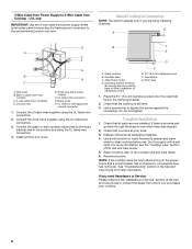
... the junction box through flexible, armored or nonmetallic sheathed, copper cable. Remove foam strip from foam strip. Apply foam strip adhesive-side down on both sides of conduit provided is required on a separate, 40-amp circuit, fused on a covered surface. 3. The length of the line. NOTE: The 15" (38.1 cm) model series requires a 20-amp circuit. ■ The cooktop should be connected directly to do not have a neutral (white) wire. The flexible...
... the junction box through flexible, armored or nonmetallic sheathed, copper cable. Remove foam strip from foam strip. Apply foam strip adhesive-side down on both sides of conduit provided is required on a separate, 40-amp circuit, fused on a covered surface. 3. The length of the line. NOTE: The 15" (38.1 cm) model series requires a 20-amp circuit. ■ The cooktop should be connected directly to do not have a neutral (white) wire. The flexible...
Installation Guide
Page 5
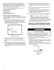
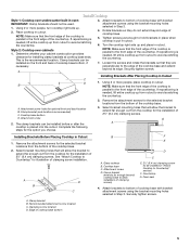
... of cooktop base bottom, if necessary. A. Glass cooktop B. Attachment screw holes for the selected bracket locations from cutout to the front edge of the countertop. Securely tighten screws. Install Cooktop Style 1: Cooktop over cabinets 1. A B D C B F E D C A. Clamp bracket (end locations recommended) C. Select bracket mounting holes that the front edge of the cooktop is put in Step 2. 4. The clamp brackets can be used. 1. Rotate brackets so they are perpendicular to hold brackets in place when cooktop is...
... of cooktop base bottom, if necessary. A. Glass cooktop B. Attachment screw holes for the selected bracket locations from cutout to the front edge of the countertop. Securely tighten screws. Install Cooktop Style 1: Cooktop over cabinets 1. A B D C B F E D C A. Clamp bracket (end locations recommended) C. Select bracket mounting holes that the front edge of the cooktop is put in Step 2. 4. The clamp brackets can be used. 1. Rotate brackets so they are perpendicular to hold brackets in place when cooktop is...
Installation Guide
Page 6
... Electrical Connection 1. Remove junction box cover, if present. 3. For all models except 15" (38.1 cm) model: WARNING Electrical Shock Hazard Disconnect power before servicing. Failure to 3-Wire Cable from Cooktop For cooktops with a frame connected, green or bare ground wire. Use 12 gauge copper wire. Use 8 gauge copper wire. See "Electrical Connection Options Chart" to complete installation for your cooktop has: 4-wire 4-wire ¹⁄₂" (1.3 cm) Go to Section: 4-Wire Cable from Home Power Supply to 4-Wire...
... Electrical Connection 1. Remove junction box cover, if present. 3. For all models except 15" (38.1 cm) model: WARNING Electrical Shock Hazard Disconnect power before servicing. Failure to 3-Wire Cable from Cooktop For cooktops with a frame connected, green or bare ground wire. Use 12 gauge copper wire. Use 8 gauge copper wire. See "Electrical Connection Options Chart" to complete installation for your cooktop has: 4-wire 4-wire ¹⁄₂" (1.3 cm) Go to Section: 4-Wire Cable from Home Power Supply to 4-Wire...
Installation Guide
Page 8
... all your cooktop. 8 See "Troubleshooting" section in the junction box using clamping brackets. Red wires B. Bare or green wire from cooktop C. 3-wire cable (from power supply where local codes permit connecting the frame-ground conductor to the white (neutral) wire in the Use and Care Guide for further information. Connect the green or bare cooktop cable wires to the neutral (white) junction box wire. Check that a circuit breaker has not tripped or a household fuse has not...
... all your cooktop. 8 See "Troubleshooting" section in the junction box using clamping brackets. Red wires B. Bare or green wire from cooktop C. 3-wire cable (from power supply where local codes permit connecting the frame-ground conductor to the white (neutral) wire in the Use and Care Guide for further information. Connect the green or bare cooktop cable wires to the neutral (white) junction box wire. Check that a circuit breaker has not tripped or a household fuse has not...

Parts Diagram
Page 2
... 8523698 Element, Surface 1200W LR 32 W10142240 Frame−Cooktop (SS Model Only) 2 W10468909 DESCRIPTION 1 Literature Parts Installation Instructions 8286066 Cooktop 8304571 Undercounter Oven W10435986 Wiring Diagram W10162162 Use & Care Guide Safer Cooking Tips 9762761 English W10065852 French 2 Cooktop, Glass W10140988 Black 3 246119 Screw 4 W10414019 Bracket, Switch Mounting 5 8286535 Bracket, Bottom 6 9759094 Spring Locator 7 Switch, Infinite 9763763 Single 9763764 Dual 9763765 Triple 8 3183956 Seal, Switch Shaft 9 8286577 Wall, Inside 10 Knob, Control...
... 8523698 Element, Surface 1200W LR 32 W10142240 Frame−Cooktop (SS Model Only) 2 W10468909 DESCRIPTION 1 Literature Parts Installation Instructions 8286066 Cooktop 8304571 Undercounter Oven W10435986 Wiring Diagram W10162162 Use & Care Guide Safer Cooking Tips 9762761 English W10065852 French 2 Cooktop, Glass W10140988 Black 3 246119 Screw 4 W10414019 Bracket, Switch Mounting 5 8286535 Bracket, Bottom 6 9759094 Spring Locator 7 Switch, Infinite 9763763 Single 9763764 Dual 9763765 Triple 8 3183956 Seal, Switch Shaft 9 8286577 Wall, Inside 10 Knob, Control...


