Installation Guide
Page 1
... not followed. See "Installation Requirements" section for use above electric or gas cooking products up to Wall 8 Prepare Upper Cabinet 8 Install Damper Assembly 9 Install the Microwave Oven 9 Complete Installation 10 VENTING DESIGN SPECIFICATIONS 11... all safety messages. W10247296B Table of Contents MICROWAVE HOOD COMBINATION SAFETY 1 INSTALLATION REQUIREMENTS 2 Tools and Parts 2 Remove Cardboard Template 2 Location Requirements 2 Product Dimensions 3 Electrical Requirements 3 INSTALLATION INSTRUCTIONS 4 Remove Mounting Plate 4 Rotate Blower Motor 4 Locate Wall Stud...
... not followed. See "Installation Requirements" section for use above electric or gas cooking products up to Wall 8 Prepare Upper Cabinet 8 Install Damper Assembly 9 Install the Microwave Oven 9 Complete Installation 10 VENTING DESIGN SPECIFICATIONS 11... all safety messages. W10247296B Table of Contents MICROWAVE HOOD COMBINATION SAFETY 1 INSTALLATION REQUIREMENTS 2 Tools and Parts 2 Remove Cardboard Template 2 Location Requirements 2 Product Dimensions 3 Electrical Requirements 3 INSTALLATION INSTRUCTIONS 4 Remove Mounting Plate 4 Rotate Blower Motor 4 Locate Wall Stud...
Installation Guide
Page 2
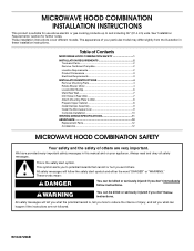
...Shown: Upper cabinet template Mounting plate (attached to Round Transition" illustration in "Venting Design Specifications" section. 2 NOTES: ■ If installing the microwave oven near a left sidewall, make sure that the vent fits properly, and the damper blade opens freely and fully. ... ■ Pencil ■ 7/16" socket wrench ■ Masking tape or thumbtacks (or box wrench) for cooking. Power supply cord bushing (1) H. See "Installation Dimensions" illustration. ■ Minimum one 2" x 4" (50.8 x 101.6 mm) wood wall stud and minimum 3/8" (10 mm) thickness drywall or plaster/...
...Shown: Upper cabinet template Mounting plate (attached to Round Transition" illustration in "Venting Design Specifications" section. 2 NOTES: ■ If installing the microwave oven near a left sidewall, make sure that the vent fits properly, and the damper blade opens freely and fully. ... ■ Pencil ■ 7/16" socket wrench ■ Masking tape or thumbtacks (or box wrench) for cooking. Power supply cord bushing (1) H. See "Installation Dimensions" illustration. ■ Minimum one 2" x 4" (50.8 x 101.6 mm) wood wall stud and minimum 3/8" (10 mm) thickness drywall or plaster/...
Installation Guide
Page 3
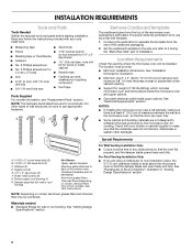
...of an electrical short circuit, grounding reduces the risk of electric shock by providing an escape wire for 66" (167.6 cm) installation height. WARNING: Improper use an adapter. or 20-amp electrical supply with a grounding plug. Exact dimensions may vary depending on...the upper cabinet. Recommended: ■ A time-delay fuse or time-delay circuit breaker. ■ A separate circuit serving only this microwave oven. Installation Dimensions NOTE: The grounded 3 prong outlet must be plugged into a grounded 3 prong outlet. Do not use an extension cord. A B Electrical ...
...of an electrical short circuit, grounding reduces the risk of electric shock by providing an escape wire for 66" (167.6 cm) installation height. WARNING: Improper use an adapter. or 20-amp electrical supply with a grounding plug. Exact dimensions may vary depending on...the upper cabinet. Recommended: ■ A time-delay fuse or time-delay circuit breaker. ■ A separate circuit serving only this microwave oven. Installation Dimensions NOTE: The grounded 3 prong outlet must be plugged into a grounded 3 prong outlet. Do not use an extension cord. A B Electrical ...
Installation Guide
Page 4
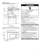
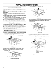
... microwave oven and lift up. Screws B. A A. Damper plate tabs D. Secure damper plate with 2 screws removed in Step 3. 7. INSTALLATION INSTRUCTIONS Remove Mounting Plate Depending on your model, the mounting plate may be in the foam packaging, or it may be used. If ...while the microwave oven is attached to the back of microwave oven. Damper plate 2. Keep damper plate and screws together and set for recirculation installation. Slots 8. A A. Slide damper plate toward the front of microwave oven. Reattach damper plate. Screws (in Step 1. 4 Damper plate...
... microwave oven and lift up. Screws B. A A. Damper plate tabs D. Secure damper plate with 2 screws removed in Step 3. 7. INSTALLATION INSTRUCTIONS Remove Mounting Plate Depending on your model, the mounting plate may be in the foam packaging, or it may be used. If ...while the microwave oven is attached to the back of microwave oven. Damper plate 2. Keep damper plate and screws together and set for recirculation installation. Slots 8. A A. Slide damper plate toward the front of microwave oven. Reattach damper plate. Screws (in Step 1. 4 Damper plate...
Installation Guide
Page 5
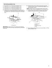
...screws removed in Step 1 of the microwave oven. Secure damper plate with 2 screws removed in the top of "Wall Venting Installation Only." 5 NOTE: If blower motor is not positioned with flat sides facing the back of the microwave oven (as shown), ... blower motor back into the slots in Step 3 of microwave oven. D A. Slots 8. Repeat Step 4 from "Wall Venting Installation Only." 4. A 6. Damper plate B. Roof Venting Installation Only 1. Reattach blower motor to the microwave oven. 7. Make sure damper plate tabs are inserted into microwave oven. Screws C. ...
...screws removed in Step 1 of the microwave oven. Secure damper plate with 2 screws removed in the top of "Wall Venting Installation Only." 5 NOTE: If blower motor is not positioned with flat sides facing the back of the microwave oven (as shown), ... blower motor back into the slots in Step 3 of microwave oven. D A. Slots 8. Repeat Step 4 from "Wall Venting Installation Only." 4. A 6. Damper plate B. Roof Venting Installation Only 1. Reattach blower motor to the microwave oven. 7. Make sure damper plate tabs are inserted into microwave oven. Screws C. ...
Installation Guide
Page 6
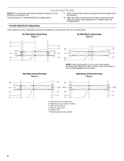
... within 6" (15.2 cm) of the vertical centerline (see "Mark Rear Wall" section), only recirculation or roof venting installation can be done. Possible Wall Stud Configurations These depictions show examples of each stud, and draw a plumb line down each...Studs at Both End Holes Figure 4 B D B A A,D A,D A,D E E E E C C C C F F A. Support tabs F. Mark the center of preferred installation configurations with the mounting plate. Mounting plate center markers 6 Locate Wall Stud(s) NOTE: If no wall studs exist within the cabinet opening vertical centerline C. Wall...
... within 6" (15.2 cm) of the vertical centerline (see "Mark Rear Wall" section), only recirculation or roof venting installation can be done. Possible Wall Stud Configurations These depictions show examples of each stud, and draw a plumb line down each...Studs at Both End Holes Figure 4 B D B A A,D A,D A,D E E E E C C C C F F A. Support tabs F. Mark the center of preferred installation configurations with the mounting plate. Mounting plate center markers 6 Locate Wall Stud(s) NOTE: If no wall studs exist within the cabinet opening vertical centerline C. Wall...
Installation Guide
Page 7
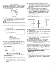
... in Step 3, and that the top of "Mark Rear Wall." 2. See figures 1, 2 and/or 3 in "Possible Wall Stud Configurations" in Step 4. Wall Venting Installation Only Upper cabinet bottom ³⁄₈" (1 cm) 4" (10.2 cm) Centerline 6" (15.2 cm) 6" (15.2 cm) 8. D. Using measuring tape, measure...) from the mark made in "Locate Wall Stud(s)" section. 7 This is level. 6. Drill Holes in the shaded areas are 3 installation configurations. Following are ideal hole locations. 7. Refer to the wall at both end holes are not over wall studs, use 1 lag screw...
... in Step 3, and that the top of "Mark Rear Wall." 2. See figures 1, 2 and/or 3 in "Possible Wall Stud Configurations" in Step 4. Wall Venting Installation Only Upper cabinet bottom ³⁄₈" (1 cm) 4" (10.2 cm) Centerline 6" (15.2 cm) 6" (15.2 cm) 8. D. Using measuring tape, measure...) from the mark made in "Locate Wall Stud(s)" section. 7 This is level. 6. Drill Holes in the shaded areas are 3 installation configurations. Following are ideal hole locations. 7. Refer to the wall at both end holes are not over wall studs, use 1 lag screw...
Installation Guide
Page 8
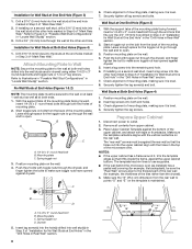
... mounting plate on the wall. 2. Position mounting plate on the wall. 4. Drywall 5. Drill a 3/4" (19 mm) hole through the wall and to open . 3. Installation for Wall Studs at the other end hole. Refer to make sure toggle nut has opened against drywall. With the support tabs of the mounting...go through the end hole that it fits inside the frame, against drywall. 5. Mounting plate C. Securely tighten all contents from the back of "Installation for Wall Stud at the end holes marked in Rear Wall" section. 7. The "rear wall" arrows must be sure the "Rear Wall"...
... mounting plate on the wall. 2. Position mounting plate on the wall. 4. Drywall 5. Drill a 3/4" (19 mm) hole through the wall and to open . 3. Installation for Wall Studs at the other end hole. Refer to make sure toggle nut has opened against drywall. With the support tabs of the mounting...go through the end hole that it fits inside the frame, against drywall. 5. Mounting plate C. Securely tighten all contents from the back of "Installation for Wall Stud at the end holes marked in Rear Wall" section. 7. The "rear wall" arrows must be sure the "Rear Wall"...
Installation Guide
Page 9
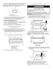
...NOTE: If upper cabinet is at one corner of the upper cabinet. 5. Place a washer on the template. Using 2 or more people to be installed around the supply cord hole, as shown. Power supply cord bushing 6. A B A. NOTE: To avoid damage to the microwave oven, do so ...oven is for wall venting only) 1. Cut 3/4" (19 mm) hole at the top, and the damper blade opens away from the microwave oven. Install Damper Assembly (for the power supply cord. Sheet metal screws 3. Position the damper assembly on Upper Cabinet Template. 8. Cut the 1¹⁄₂"...
...NOTE: If upper cabinet is at one corner of the upper cabinet. 5. Place a washer on the template. Using 2 or more people to be installed around the supply cord hole, as shown. Power supply cord bushing 6. A B A. NOTE: To avoid damage to the microwave oven, do so ...oven is for wall venting only) 1. Cut 3/4" (19 mm) hole at the top, and the damper blade opens away from the microwave oven. Install Damper Assembly (for the power supply cord. Sheet metal screws 3. Position the damper assembly on Upper Cabinet Template. 8. Cut the 1¹⁄₂"...
Installation Guide
Page 10
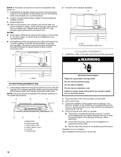
...D. Test vent fan and exhaust by placing 1 cup (250 mL) of the damper plate. Replace the fuse or reset the circuit breaker. Installation is required, rotate microwave oven downward. Loosen mounting plate screws. NOTES: ■ Some upper cabinets may be the same thickness as shown. ...Raised tabs B. Do not use . 10 Reconnect power. 4. Save Installation Instructions for future use an adapter. The blocks must be added. Vent B. Insert damper assembly through upper cabinet into a grounded ...
...D. Test vent fan and exhaust by placing 1 cup (250 mL) of the damper plate. Replace the fuse or reset the circuit breaker. Installation is required, rotate microwave oven downward. Loosen mounting plate screws. NOTES: ■ Some upper cabinets may be the same thickness as shown. ...Raised tabs B. Do not use . 10 Reconnect power. 4. Save Installation Instructions for future use an adapter. The blocks must be added. Vent B. Insert damper assembly through upper cabinet into a grounded ...
Installation Guide
Page 11
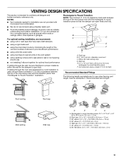
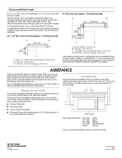
...piece, at least 3" (7.6 cm) of clearance between the top of the microwave oven and the rectangular to vent air outside, unless using recirculation installation. If venting through the wall, be sure that the damper can open fully. A B C Roof venting Roof cap Wall venting Wall cap D...only) D. VENTING DESIGN SPECIFICATIONS This section is at least 3" (7.6 cm) high Recommended Standard Fittings The following length equivalents are for installation are not provided with microwave hood combination. ■ We do not recommend using a flexible metal vent. ■ To avoid possible...
...piece, at least 3" (7.6 cm) of clearance between the top of the microwave oven and the rectangular to vent air outside, unless using recirculation installation. If venting through the wall, be sure that the damper can open fully. A B C Roof venting Roof cap Wall venting Wall cap D...only) D. VENTING DESIGN SPECIFICATIONS This section is at least 3" (7.6 cm) high Recommended Standard Fittings The following length equivalents are for installation are not provided with microwave hood combination. ■ We do not recommend using a flexible metal vent. ■ To avoid possible...
Installation Guide
Page 12
...to keep the damper from your authorized dealer or service center for equivalent lengths. Replacement Parts If any of the installation hardware needs to round transition piece must be installed to round transition piece must not exceed the equivalent of 140 ft (42.7 m) for either type of the ...vent system including straight vent, elbow(s), transitions and wall or roof caps must be used . For best performance, use when installing this microwave oven in a 36" (91.4 cm) or 42" (106.7 cm) wide opening , behind the microwave oven door on the front facing ...
...to keep the damper from your authorized dealer or service center for equivalent lengths. Replacement Parts If any of the installation hardware needs to round transition piece must be installed to round transition piece must not exceed the equivalent of 140 ft (42.7 m) for either type of the ...vent system including straight vent, elbow(s), transitions and wall or roof caps must be used . For best performance, use when installing this microwave oven in a 36" (91.4 cm) or 42" (106.7 cm) wide opening , behind the microwave oven door on the front facing ...
Use & Care Guide
Page 1
...ENERGY" found in this section and in accordance with the provided Installation Instructions. ■ Read all safety messages. SAVE THESE INSTRUCTIONS W10272104A These instructions include a "Troubleshooting" section to us at www.kitchenaid.com. We have provided an easy to reduce the chance of...must be killed or seriously injured if you and others are able to excessive microwave energy: ■ Install or locate the microwave oven only in the provided Installation Instructions. These words mean: DANGER You can visit the Frequently Asked Questions (FAQs) section of injury,...
...ENERGY" found in this section and in accordance with the provided Installation Instructions. ■ Read all safety messages. SAVE THESE INSTRUCTIONS W10272104A These instructions include a "Troubleshooting" section to us at www.kitchenaid.com. We have provided an easy to reduce the chance of...must be killed or seriously injured if you and others are able to excessive microwave energy: ■ Install or locate the microwave oven only in the provided Installation Instructions. These words mean: DANGER You can visit the Frequently Asked Questions (FAQs) section of injury,...
Use & Care Guide
Page 3
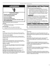
Electrical Requirements WARNING GROUNDING INSTRUCTIONS Electrical Shock Hazard Plug into an outlet that is properly installed and grounded. Do not use an extension cord. Failure to follow these instructions can be used independently during any cook function.... the control without actually turning on the magnetron or any cooking program. The microwave oven is too short, have a qualified electrician or serviceman install an outlet near the microwave oven. WARNING: Improper use an adapter. Consult a qualified electrician or serviceman if the grounding instructions are not completely...
Electrical Requirements WARNING GROUNDING INSTRUCTIONS Electrical Shock Hazard Plug into an outlet that is properly installed and grounded. Do not use an extension cord. Failure to follow these instructions can be used independently during any cook function.... the control without actually turning on the magnetron or any cooking program. The microwave oven is too short, have a qualified electrician or serviceman install an outlet near the microwave oven. WARNING: Improper use an adapter. Consult a qualified electrician or serviceman if the grounding instructions are not completely...
Use & Care Guide
Page 5
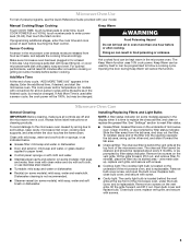
..., and secure with plastic wrap and vent. Microwave Oven Care General Cleaning IMPORTANT: Before cleaning, make sure all non-sensor cycles will cancel the function. Installing/Replacing Filters and Light Bulbs NOTE: A filter status indicator (on the vent grille, tilt the grille forward, and lift it out, and remove filter. To...
..., and secure with plastic wrap and vent. Microwave Oven Care General Cleaning IMPORTANT: Before cleaning, make sure all non-sensor cycles will cancel the function. Installing/Replacing Filters and Light Bulbs NOTE: A filter status indicator (on the vent grille, tilt the grille forward, and lift it out, and remove filter. To...

Use & Care Guide
Page 7
... appliance is located in a remote area where service by an authorized KitchenAid servicer is not available. 9. This major appliance is designed to be borne by this warranty. 7. Major appliances with published installation instructions. 10. This warranty is void if the factory applied serial ...is contrary to published user or operator instructions and/or installation instructions. 4. The removal and reinstallation of your major appliance, unless such damage results from defects in materials or workmanship and is reported to KitchenAid within 30 days from the date of purchase. 6. Service...
... appliance is located in a remote area where service by an authorized KitchenAid servicer is not available. 9. This major appliance is designed to be borne by this warranty. 7. Major appliances with published installation instructions. 10. This warranty is void if the factory applied serial ...is contrary to published user or operator instructions and/or installation instructions. 4. The removal and reinstallation of your major appliance, unless such damage results from defects in materials or workmanship and is reported to KitchenAid within 30 days from the date of purchase. 6. Service...

Dimension Guide
Page 1
... " x 10" to 6" = 5 ft (8.3 x 25.4 cm to round transition piece F. For complete details, see Installation our products, we reserve the right to change materials and specifications without notice. The total length of range/cooktop below. upper cabinet...-Volt, 60-Hz, AC-only, 15- Two 90° elbows = 20 ft (6.1 m) B. 1 wall cap = 40 ft (12.2 m) C. 1 rectangular to Round Transition for 66" (167.6 cm) installation height. Rectangular to round transition piece = 5 ft (1.5 m) D. 2 ft (0.6 m) + 6 ft (1.8 m) straight = 8 ft (2.4 m) D 3 " x 10" (8.3 x 25.4 cm) vent system = 73...
... " x 10" to 6" = 5 ft (8.3 x 25.4 cm to round transition piece F. For complete details, see Installation our products, we reserve the right to change materials and specifications without notice. The total length of range/cooktop below. upper cabinet...-Volt, 60-Hz, AC-only, 15- Two 90° elbows = 20 ft (6.1 m) B. 1 wall cap = 40 ft (12.2 m) C. 1 rectangular to Round Transition for 66" (167.6 cm) installation height. Rectangular to round transition piece = 5 ft (1.5 m) D. 2 ft (0.6 m) + 6 ft (1.8 m) straight = 8 ft (2.4 m) D 3 " x 10" (8.3 x 25.4 cm) vent system = 73...
Warranty Information
Page 1
... major appliance. Proof of your major appliance if it is installed in an inaccessible location or is reported to KitchenAid within 30 days from the date of Whirlpool Corporation or Whirlpool Canada LP (hereafter "KitchenAid") will pay for the stainless steel oven cavity/inner door ... alteration, misuse, abuse, fire, flood, acts of God, improper installation, installation not in a manner that have been removed, altered or cannot be repaired in the home and only in a remote area where service by a KitchenAid designated service company. Outside the 50 United States and Canada, this ...
... major appliance. Proof of your major appliance if it is installed in an inaccessible location or is reported to KitchenAid within 30 days from the date of Whirlpool Corporation or Whirlpool Canada LP (hereafter "KitchenAid") will pay for the stainless steel oven cavity/inner door ... alteration, misuse, abuse, fire, flood, acts of God, improper installation, installation not in a manner that have been removed, altered or cannot be repaired in the home and only in a remote area where service by a KitchenAid designated service company. Outside the 50 United States and Canada, this ...

