Installation Guide
Page 1
... installation instructions cover different models. Table of Contents MICROWAVE HOOD COMBINATION SAFETY 1 INSTALLATION REQUIREMENTS 2 Tools and Parts 2 Remove Cardboard Template 2 Location Requirements 2 Product Dimensions 3 Electrical Requirements 3 INSTALLATION INSTRUCTIONS 4 Remove Mounting Plate 4 Rotate Blower Motor 4 Locate Wall Stud(s 6 Mark Rear Wall 7 Drill Holes in this manual and on your particular model may differ slightly from the illustration in these installation instructions. We have provided many important safety messages in Rear Wall 7 Attach Mounting Plate...
... installation instructions cover different models. Table of Contents MICROWAVE HOOD COMBINATION SAFETY 1 INSTALLATION REQUIREMENTS 2 Tools and Parts 2 Remove Cardboard Template 2 Location Requirements 2 Product Dimensions 3 Electrical Requirements 3 INSTALLATION INSTRUCTIONS 4 Remove Mounting Plate 4 Rotate Blower Motor 4 Locate Wall Stud(s 6 Mark Rear Wall 7 Drill Holes in this manual and on your particular model may differ slightly from the illustration in these installation instructions. We have provided many important safety messages in Rear Wall 7 Attach Mounting Plate...
Installation Guide
Page 2
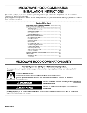
... instructions provided with your builder or cabinet supplier to back of microwave oven) Cardboard template (part of packaging) Aluminum grease filters Charcoal filters (Depending on model, aluminum grease filter and charcoal filter may not be sure to it during the "Mark Rear Wall" part of 150 lbs (68 kg), which includes microwave oven and items placed inside the microwave oven and upper cabinet. ■ Grounded electrical outlet inside the perforation is for wall or roof venting) Not Shown: Upper cabinet template Mounting plate...
... instructions provided with your builder or cabinet supplier to back of microwave oven) Cardboard template (part of packaging) Aluminum grease filters Charcoal filters (Depending on model, aluminum grease filter and charcoal filter may not be sure to it during the "Mark Rear Wall" part of 150 lbs (68 kg), which includes microwave oven and items placed inside the microwave oven and upper cabinet. ■ Grounded electrical outlet inside the perforation is for wall or roof venting) Not Shown: Upper cabinet template Mounting plate...
Installation Guide
Page 3
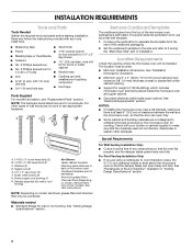
.... Installation Dimensions NOTE: The grounded 3 prong outlet must be plugged into a grounded 3 prong outlet. Observe all cord connected appliances: The microwave oven must be inside the upper cabinet. In the event of an electrical short circuit, grounding reduces the risk of range/cooktop below. Do not use of the grounding plug can result in a risk of electric shock. If the power supply cord is properly installed...
.... Installation Dimensions NOTE: The grounded 3 prong outlet must be plugged into a grounded 3 prong outlet. Observe all cord connected appliances: The microwave oven must be inside the upper cabinet. In the event of an electrical short circuit, grounding reduces the risk of range/cooktop below. Do not use of the grounding plug can result in a risk of electric shock. If the power supply cord is properly installed...
Installation Guide
Page 4
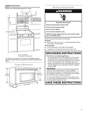
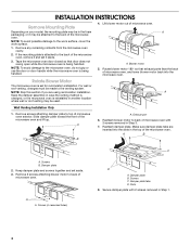
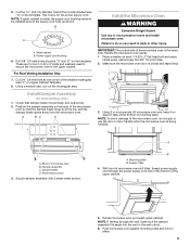
...microwave oven with 2 screws removed in Step 1. 4 A Keep the damper assembly in case the venting method is changed, or the microwave oven is set for recirculation installation. A B A. A B C A. Slots 8. Damper plate 2. Screws C. A A. Remove 2 screws attaching blower motor to the work surface, cover the work surface. 1. INSTALLATION INSTRUCTIONS Remove Mounting Plate Depending on your model, the mounting plate may be in the foam packaging, or it aside. 3. Remove any remaining contents from the microwave oven cavity. 2. Tape the microwave oven door closed so that exhaust...
...microwave oven with 2 screws removed in Step 1. 4 A Keep the damper assembly in case the venting method is changed, or the microwave oven is set for recirculation installation. A B A. A B C A. Slots 8. Damper plate 2. Screws C. A A. Remove 2 screws attaching blower motor to the work surface, cover the work surface. 1. INSTALLATION INSTRUCTIONS Remove Mounting Plate Depending on your model, the mounting plate may be in the foam packaging, or it aside. 3. Remove any remaining contents from the microwave oven cavity. 2. Tape the microwave oven door closed so that exhaust...
Installation Guide
Page 5
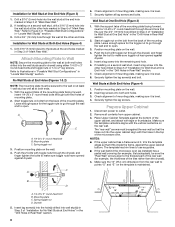
... into microwave oven. D A. Roof Venting Installation Only 1. A 6. Reattach damper plate. Damper plate tabs D. NOTE: If blower motor is not positioned with flat sides facing the back of the microwave oven (as shown), performance will be reattached to back of microwave oven with 2 screws removed in the top of "Wall Venting Installation Only." 5 Repeat Step 3 from "Wall Venting Installation Only." 2. Secure damper plate with 2 screws removed in Step 3 cannot be poor. Repeat Step 1 from "Wall Venting Installation Only." 4. Exhaust port...
... into microwave oven. D A. Roof Venting Installation Only 1. A 6. Reattach damper plate. Damper plate tabs D. NOTE: If blower motor is not positioned with flat sides facing the back of the microwave oven (as shown), performance will be reattached to back of microwave oven with 2 screws removed in the top of "Wall Venting Installation Only." 5 Repeat Step 3 from "Wall Venting Installation Only." 2. Secure damper plate with 2 screws removed in Step 3 cannot be poor. Repeat Step 1 from "Wall Venting Installation Only." 4. Exhaust port...
Installation Guide
Page 6
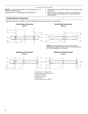
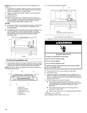
... stud, and draw a plumb line down each stud center. Cabinet opening , do not install the microwave oven. 1. Holes for lag screws E. See illustrations in "Possible Wall Stud Configurations." 2. See illustrations in "Possible Wall Stud Configurations." Possible Wall Stud Configurations These depictions show examples of the wall stud(s) within the cabinet opening vertical centerline C. Using a stud finder, locate the edges of preferred installation configurations with the mounting plate.
... stud, and draw a plumb line down each stud center. Cabinet opening , do not install the microwave oven. 1. Holes for lag screws E. See illustrations in "Possible Wall Stud Configurations." 2. See illustrations in "Possible Wall Stud Configurations." Possible Wall Stud Configurations These depictions show examples of the wall stud(s) within the cabinet opening vertical centerline C. Using a stud finder, locate the edges of preferred installation configurations with the mounting plate.
Installation Guide
Page 7
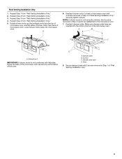
... the cardboard template to the centerline on a minimum of 1 wall stud, preferably 2, using a minimum of 1 lag screw, preferably 2. 1. Cardboard template C. Make sure the mounting plate is the venting cutout area. 13. Set the mounting plate aside. Measure down from the bottom edge of the upper cabinet. 9. This is level. 6. or if both end holes are over a wall stud, use 1 lag screw and one corner of the cutout area. 14. Rear wall B. Mark...
... the cardboard template to the centerline on a minimum of 1 wall stud, preferably 2, using a minimum of 1 lag screw, preferably 2. 1. Cardboard template C. Make sure the mounting plate is the venting cutout area. 13. Set the mounting plate aside. Measure down from the bottom edge of the upper cabinet. 9. This is level. 6. or if both end holes are over a wall stud, use 1 lag screw and one corner of the cutout area. 14. Rear wall B. Mark...
Installation Guide
Page 8
... Cabinet 1. Spring toggle nut D. Position mounting plate on the rear wall. Check alignment of mounting plate, making sure it fits inside the frame, against drywall. 5. Insert a lag screw into both end holes drilled into wall stud(s) in "Locate Wall Stud(s)" section. 3. Wall Studs at both end holes. 3. Insert lag screws into the remaining end hole. 6. Disconnect power to the wall on the template is level. 7. Spring toggle nut 3. Remove...
... Cabinet 1. Spring toggle nut D. Position mounting plate on the rear wall. Check alignment of mounting plate, making sure it fits inside the frame, against drywall. 5. Insert a lag screw into both end holes drilled into wall stud(s) in "Locate Wall Stud(s)" section. 3. Wall Studs at both end holes. 3. Insert lag screws into the remaining end hole. 6. Disconnect power to the wall on the template is level. 7. Spring toggle nut 3. Remove...
Installation Guide
Page 9
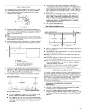
.... 9 Mounting plate B. B A A. Check that the damper blade hinge is being handled. Damper assembly C. Damper blade D. A B A. Metal cabinet B. A. Support tabs 4. 5. This hole is metal, the supply cord bushing needs to do not grip or use the door or door handle while the microwave oven is at the bottom of the microwave oven is closed and taped shut. 3. Power supply cord bushing 6. Drill 3/8" (10 mm) holes at the circular shaded area "G" on the template...
.... 9 Mounting plate B. B A A. Check that the damper blade hinge is being handled. Damper assembly C. Damper blade D. A B A. Metal cabinet B. A. Support tabs 4. 5. This hole is metal, the supply cord bushing needs to do not grip or use the door or door handle while the microwave oven is at the bottom of the microwave oven is closed and taped shut. 3. Power supply cord bushing 6. Drill 3/8" (10 mm) holes at the circular shaded area "G" on the template...
Installation Guide
Page 10
... to damper assembly. Loosen mounting plate screws. Test vent fan and exhaust by placing 1 cup (250 mL) of 1 minute at 100% power. If the microwave oven does not operate: ■ Check that a household fuse has not blown, or that the power supply cord is no gap between the upper cabinet bottom and the microwave oven. Using 2 or more people, lift microwave oven off of mounting plate, and set aside on the turntable, and programming a cook time of water on a covered...
... to damper assembly. Loosen mounting plate screws. Test vent fan and exhaust by placing 1 cup (250 mL) of 1 minute at 100% power. If the microwave oven does not operate: ■ Check that a household fuse has not blown, or that the power supply cord is no gap between the upper cabinet bottom and the microwave oven. Using 2 or more people, lift microwave oven off of mounting plate, and set aside on the turntable, and programming a cook time of water on a covered...
Installation Guide
Page 12
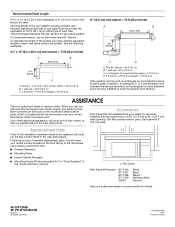
... of each vent piece used . Each panel is a list of available replacement parts. W10247296B SP PN W10345003B © 2010. Two 90° elbows = 20 ft (6.1 m) B. 1 wall cap = 40 ft (12.2 m) C. 1 rectangular to round transition piece = 5 ft (1.5 m) D. 2 ft (0.6 m) + 6 ft (1.8 m) straight = 8 ft (2.4 m) If the existing vent is located behind the door. ■ Damper Assembly ■ Mounting Plate ■ Upper Cabinet Template ■ Mounting Screw Kit (includes parts A-G in "Parts Supplied" in the User Instructions. Following...
... of each vent piece used . Each panel is a list of available replacement parts. W10247296B SP PN W10345003B © 2010. Two 90° elbows = 20 ft (6.1 m) B. 1 wall cap = 40 ft (12.2 m) C. 1 rectangular to round transition piece = 5 ft (1.5 m) D. 2 ft (0.6 m) + 6 ft (1.8 m) straight = 8 ft (2.4 m) If the existing vent is located behind the door. ■ Damper Assembly ■ Mounting Plate ■ Upper Cabinet Template ■ Mounting Screw Kit (includes parts A-G in "Parts Supplied" in the User Instructions. Following...
Use & Care Guide
Page 1
MICROWAVE HOOD COMBINATION USER INSTRUCTIONS Thank you need further assistance using your KitchenAid microwave hood combination, please contact us that can visit the Frequently Asked Questions (FAQs) section of the microwave oven opening, behind the door. For your convenience, we have provided an easy to help you through any problems you what the potential hazard is, tell you how to us at www.kitchenaid.com. These instructions include a "Troubleshooting" section...
MICROWAVE HOOD COMBINATION USER INSTRUCTIONS Thank you need further assistance using your KitchenAid microwave hood combination, please contact us that can visit the Frequently Asked Questions (FAQs) section of the microwave oven opening, behind the door. For your convenience, we have provided an easy to help you through any problems you what the potential hazard is, tell you how to us at www.kitchenaid.com. These instructions include a "Troubleshooting" section...

Use & Care Guide
Page 2
... on the microwave oven. ■ Do not store this oven with the door open since open-door operation can burn off power at the fuse or circuit breaker panel. - Grease should be adjusted or repaired by qualified service personnel. Do not use the microwave oven near a swimming pool, or similar locations. ■ Do not immerse cord or plug in convection, combination, grill or "PAN BROWN" mode (on models with maximum width of the oven with any...
... on the microwave oven. ■ Do not store this oven with the door open since open-door operation can burn off power at the fuse or circuit breaker panel. - Grease should be adjusted or repaired by qualified service personnel. Do not use the microwave oven near a swimming pool, or similar locations. ■ Do not immerse cord or plug in convection, combination, grill or "PAN BROWN" mode (on models with maximum width of the oven with any...
Use & Care Guide
Page 3
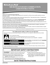
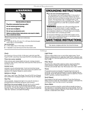
... an electrical short circuit, grounding reduces the risk of the FCC Rules. WARNING: Improper use an extension cord. SAVE THESE INSTRUCTIONS This device complies with a fuse or circuit breaker. Options or Setup Vent Timer, Light Timer, Filter Reset, Sound On/Off, Scroll Speed, Demo Mode and Language (English or French) may be adjusted. Vent Fan Various speeds, ranging from high to turn tones off , or all cord connected appliances: The microwave oven must be used...
... an electrical short circuit, grounding reduces the risk of the FCC Rules. WARNING: Improper use an extension cord. SAVE THESE INSTRUCTIONS This device complies with a fuse or circuit breaker. Options or Setup Vent Timer, Light Timer, Filter Reset, Sound On/Off, Scroll Speed, Demo Mode and Language (English or French) may be adjusted. Vent Fan Various speeds, ranging from high to turn tones off , or all cord connected appliances: The microwave oven must be used...
Use & Care Guide
Page 4
... gold or silver trim or with plates that the food be placed directly on some models): ■ Metal bakeware may be turned off during convection (bake) cycles. Use the rectangular cooking rack only for convection cycles (baking or roasting). Turntable B. If dish becomes hot and the water stays cool, do not use just the base and lid for steaming, or use the dish in the wall of cook time...
... gold or silver trim or with plates that the food be placed directly on some models): ■ Metal bakeware may be turned off during convection (bake) cycles. Use the rectangular cooking rack only for convection cycles (baking or roasting). Turntable B. If dish becomes hot and the water stays cool, do not use just the base and lid for steaming, or use the dish in the wall of cook time...
Use & Care Guide
Page 5
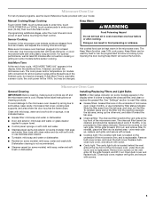
... grease filter. Remove bulb cover screw, and open the bulb cover. Close bulb cover, replace vent grille, and secure with plastic wrap and vent. Manual Cooking/Stage Cooking Touch COOK TIME, touch number pads to enter time, touch COOK POWER (if not 100%), touch number pads to soil buildup, keep cavity, microwave inlet cover, cooking rack supports, and area where the door touches the frame clean. If programming additional stages, enter the cook time and cook power of any cycle, "ADD MORE TIME 0:00" appears in the display. Enter the additional time, if desired, and start...
... grease filter. Remove bulb cover screw, and open the bulb cover. Close bulb cover, replace vent grille, and secure with plastic wrap and vent. Manual Cooking/Stage Cooking Touch COOK TIME, touch number pads to enter time, touch COOK POWER (if not 100%), touch number pads to soil buildup, keep cavity, microwave inlet cover, cooking rack supports, and area where the door touches the frame clean. If programming additional stages, enter the cook time and cook power of any cycle, "ADD MORE TIME 0:00" appears in the display. Enter the additional time, if desired, and start...

Use & Care Guide
Page 6
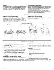
... starting of the door, remove it, then firmly close door. Make sure Demo Mode (on . Call for 5 minutes or more without the microwave oven being used. Replacement Parts Provided Accessories ■ Turntable ■ Turntable support and rollers ■ Turntable hub ■ Cooking rack (for some models) ■ Rack clip (for some models) ■ Rack support (for some models) ■ Grease filter ■ Charcoal filter ■ Cooktop light bulb ■ Cavity light bulb ■ Steamer vessel (provided with some models, if a packaging spacer is set...
... starting of the door, remove it, then firmly close door. Make sure Demo Mode (on . Call for 5 minutes or more without the microwave oven being used. Replacement Parts Provided Accessories ■ Turntable ■ Turntable support and rollers ■ Turntable hub ■ Cooking rack (for some models) ■ Rack clip (for some models) ■ Rack support (for some models) ■ Grease filter ■ Charcoal filter ■ Cooktop light bulb ■ Cavity light bulb ■ Steamer vessel (provided with some models, if a packaging spacer is set...

Use & Care Guide
Page 7
... steel oven cavity/inner door if the part rusts through tenth years from date of purchase, when this major appliance is operated and maintained according to instructions attached to or furnished with electrical or plumbing codes, or use of consumables or cleaning products not approved by a KitchenAid designated service company. ITEMS EXCLUDED FROM WARRANTY This limited warranty does not cover: 1. KITCHENAID® BUILT-IN OVEN & MICROWAVE WARRANTY LIMITED WARRANTY For...
... steel oven cavity/inner door if the part rusts through tenth years from date of purchase, when this major appliance is operated and maintained according to instructions attached to or furnished with electrical or plumbing codes, or use of consumables or cleaning products not approved by a KitchenAid designated service company. ITEMS EXCLUDED FROM WARRANTY This limited warranty does not cover: 1. KITCHENAID® BUILT-IN OVEN & MICROWAVE WARRANTY LIMITED WARRANTY For...

Dimension Guide
Page 1
... need, add the equivalent length for each vent piece used . One 3 " x 10" (8.3 x 25.4 cm) 90° elbow = 25 ft (7.6 m) B. 1 wall cap = 40 ft (12.2 m) C. 2 ft (0.6 m) + 6 ft (1.8 m) straight = 8 ft (2.4 m) A. 2" x 4" wall stud B. Exact dimensions may vary depending on type of the microwave oven and the rectangular to change materials and specifications without notice. See the following examples: A B C (401.05 cm" ) ' " (76.0 cm) CABINET OPENING DIMENSIONS...
... need, add the equivalent length for each vent piece used . One 3 " x 10" (8.3 x 25.4 cm) 90° elbow = 25 ft (7.6 m) B. 1 wall cap = 40 ft (12.2 m) C. 2 ft (0.6 m) + 6 ft (1.8 m) straight = 8 ft (2.4 m) A. 2" x 4" wall stud B. Exact dimensions may vary depending on type of the microwave oven and the rectangular to change materials and specifications without notice. See the following examples: A B C (401.05 cm" ) ' " (76.0 cm) CABINET OPENING DIMENSIONS...
Warranty Information
Page 1
...-family household use of consumables or cleaning products not approved by a KitchenAid designated service company. DISCLAIMER OF IMPLIED WARRANTIES; ITEMS EXCLUDED FROM WARRANTY This limited warranty does not cover: 1. Costs associated with the removal from your major appliance, to replace or repair house fuses, or to correct house wiring or plumbing. 2. Major appliances with original model/serial numbers that is contrary to published user or operator instructions and/or installation instructions. 4. Service must...
...-family household use of consumables or cleaning products not approved by a KitchenAid designated service company. DISCLAIMER OF IMPLIED WARRANTIES; ITEMS EXCLUDED FROM WARRANTY This limited warranty does not cover: 1. Costs associated with the removal from your major appliance, to replace or repair house fuses, or to correct house wiring or plumbing. 2. Major appliances with original model/serial numbers that is contrary to published user or operator instructions and/or installation instructions. 4. Service must...


