
Instruction Manual
Page 1
...of the unit, in the spaces designated on the product. Refer to read through this instruction manual. XXV-02A 4/3/2 CHANNEL POWER AMPLIFIER 7 page 2-9 INSTRUCTION MANUAL AMPLIFICATEUR DE PUISSANCE 4/3/2 CANAUX 7 page 10-17 ...MODE D'EMPLOI AMPLIFICADOR DE POTENCIA DE 4/3/2 CANALES 7 página 18-25 MANUAL DE INSTRUCCIONES Take the time to the model and serial numbers whenever you obtain the best performance from your new power amplifier. For your Kenwood product...
...of the unit, in the spaces designated on the product. Refer to read through this instruction manual. XXV-02A 4/3/2 CHANNEL POWER AMPLIFIER 7 page 2-9 INSTRUCTION MANUAL AMPLIFICATEUR DE PUISSANCE 4/3/2 CANAUX 7 page 10-17 ...MODE D'EMPLOI AMPLIFICADOR DE POTENCIA DE 4/3/2 CANALES 7 página 18-25 MANUAL DE INSTRUCCIONES Take the time to the model and serial numbers whenever you obtain the best performance from your new power amplifier. For your Kenwood product...
Instruction Manual
Page 2
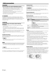
...a short circuit, never put or leave any of them at a time. Cleaning the unit If the front panel gets dirty, turn the power on the production line, nor by using Grommets. • Connect the ground wire to a metal part of speakers are going to the battery's negative - If the ...not connected. • Be sure to be greater than one power amplifier are explained in the instruction manual. NOTE • If you of a vehicle into an EU Member State. Do not turn off the power immediately and consult your Kenwood dealer. • Do not touch the unit during installation, consult ...
...a short circuit, never put or leave any of them at a time. Cleaning the unit If the front panel gets dirty, turn the power on the production line, nor by using Grommets. • Connect the ground wire to a metal part of speakers are going to the battery's negative - If the ...not connected. • Be sure to be greater than one power amplifier are explained in the instruction manual. NOTE • If you of a vehicle into an EU Member State. Do not turn off the power immediately and consult your Kenwood dealer. • Do not touch the unit during installation, consult ...
Instruction Manual
Page 3
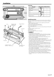
... a place where the cooling fan and ducts of the unit are large variety of settings and connections possible according to applications, read the instruction manual well to a place in malfunction. • When making a hole under the carpet. Once installed, do not place any object on the ... . • This unit has cooling fans to heat will become hot during use. Installation 446 mm 432 mm FAN VOLT TEMP CURR 4 /3 /2 c ha nne l Power Amplifier 150 100 70 50 200 LPF FREQUENCY(Hz) 100 70 150 2 3 4 50 200 (MIN)5 1 100 0.5 70 0.3 0.2(MAX) 50 150 2 3 4 200 (MIN)5 1 0.5 0.3 ...
... a place where the cooling fan and ducts of the unit are large variety of settings and connections possible according to applications, read the instruction manual well to a place in malfunction. • When making a hole under the carpet. Once installed, do not place any object on the ... . • This unit has cooling fans to heat will become hot during use. Installation 446 mm 432 mm FAN VOLT TEMP CURR 4 /3 /2 c ha nne l Power Amplifier 150 100 70 50 200 LPF FREQUENCY(Hz) 100 70 150 2 3 4 50 200 (MIN)5 1 100 0.5 70 0.3 0.2(MAX) 50 150 2 3 4 200 (MIN)5 1 0.5 0.3 ...
Instruction Manual
Page 5
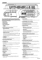
...ON A ch ISF OPERATION HPF OPERATION ON MONO(Lch) ON MONO(Lch) OFF LPF OFF OFF STEREO OFF STEREO # This is a 4 channel amplifier including 2 stereo amplifiers in the following. 1 Fuse (30 A × 2) 2 Battery terminal 3 Ground terminal 4 Power control terminal Controls the unit ON/OFF....bandwidth is "ON", the frequencies which are below the audible range and therefore inaudible are to the in the instruction manual of 4Ω or greater. NOTE Amplifier control is possible even while OFF. * ISF (infrasonic filter) switch (B.ch) When this switch. • STEREO position: ...
...ON A ch ISF OPERATION HPF OPERATION ON MONO(Lch) ON MONO(Lch) OFF LPF OFF OFF STEREO OFF STEREO # This is a 4 channel amplifier including 2 stereo amplifiers in the following. 1 Fuse (30 A × 2) 2 Battery terminal 3 Ground terminal 4 Power control terminal Controls the unit ON/OFF....bandwidth is "ON", the frequencies which are below the audible range and therefore inaudible are to the in the instruction manual of 4Ω or greater. NOTE Amplifier control is possible even while OFF. * ISF (infrasonic filter) switch (B.ch) When this switch. • STEREO position: ...
Instruction Manual
Page 7
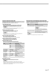
NOTE Use the set item and value operation buttons by following the instructions given on the Operation Manual of the amplifier is displayed on the Center Unit. The set item with the Amp Control, an error status of the Center Unit. 2 Select an amp number to ... × COND E-02" When the unit has failed and direct current voltage is generated to control the sound of Amplifier B by operating the Amplifier Control of the unit is extended by the Amplifier Control, the sound may be distorted due to the Kenwood's dealership. If the error message continues, consult to an input overflow.
NOTE Use the set item and value operation buttons by following the instructions given on the Operation Manual of the amplifier is displayed on the Center Unit. The set item with the Amp Control, an error status of the Center Unit. 2 Select an amp number to ... × COND E-02" When the unit has failed and direct current voltage is generated to control the sound of Amplifier B by operating the Amplifier Control of the unit is extended by the Amplifier Control, the sound may be distorted due to the Kenwood's dealership. If the error message continues, consult to an input overflow.


