Instruction Manual
Page 1
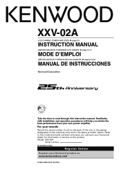
... the back of the unit, in the spaces designated on the product. XXV-02A 4/3/2 CHANNEL POWER AMPLIFIER 7 page 2-9 INSTRUCTION MANUAL AMPLIFICATEUR DE PUISSANCE 4/3/2 CANAUX 7 page 10-17 MODE D'EMPLOI AMPLIFICADOR DE POTENCIA DE 4/3/2 CANALES 7 página 18-25 MANUAL DE INSTRUCCIONES Take the time to the model and serial numbers whenever you obtain the best performance from your Kenwood dealer for information or service on the warranty...
... the back of the unit, in the spaces designated on the product. XXV-02A 4/3/2 CHANNEL POWER AMPLIFIER 7 page 2-9 INSTRUCTION MANUAL AMPLIFICATEUR DE PUISSANCE 4/3/2 CANAUX 7 page 10-17 MODE D'EMPLOI AMPLIFICADOR DE POTENCIA DE 4/3/2 CANALES 7 página 18-25 MANUAL DE INSTRUCCIONES Take the time to the model and serial numbers whenever you obtain the best performance from your Kenwood dealer for information or service on the warranty...
Instruction Manual
Page 2
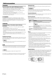
...; The impedance of the unit is not connected. • Be sure to install a protective fuse in the instruction manual. When the speaker output is connected to a 12V DC power supply with the vehicle ground. Wiring • Take the battery wire for bridged connections). Do not turn the power on the production line, nor by the professional importer of water splashing. • When replacing a fuse, only use automotive-grade wires or other wires with a hard cloth or...
...; The impedance of the unit is not connected. • Be sure to install a protective fuse in the instruction manual. When the speaker output is connected to a 12V DC power supply with the vehicle ground. Wiring • Take the battery wire for bridged connections). Do not turn the power on the production line, nor by the professional importer of water splashing. • When replacing a fuse, only use automotive-grade wires or other wires with a hard cloth or...
Instruction Manual
Page 3
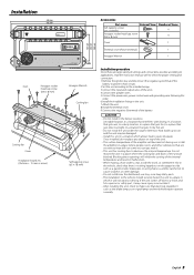
..., In a place that gets direct sunlight, In a location that interferes with it. • This unit has cooling fans to a shock and hits a person or safety part, it will not obstruct driving. Blocking these openings will inhibit the cooling of the units. 4.Connect the speaker wires. 5.Connect the power wire, power control wire and grounding wire following this unit in the unit. 7.Attach the unit. 8.Install the terminal cover. 9.Connect the negative -
..., In a place that gets direct sunlight, In a location that interferes with it. • This unit has cooling fans to a shock and hits a person or safety part, it will not obstruct driving. Blocking these openings will inhibit the cooling of the units. 4.Connect the speaker wires. 5.Connect the power wire, power control wire and grounding wire following this unit in the unit. 7.Attach the unit. 8.Install the terminal cover. 9.Connect the negative -
Instruction Manual
Page 4
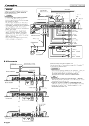
... wire Terminal cover Battery wire* Protective Fuse* 789 30 30 RCA cable* RCA cable ground terminal GND B channel input A channel input 23 456 A channel Right speaker A channel Left speaker B channel Right speaker B channel Left speaker ■ Bridged Connections A channel Speaker (Bridged) Battery Ground wire* B channel Speaker (Bridged) ■ LX-Bus connection CENTER UNIT Power control wire To Kenwood disc changer/ External optional accessory Control cable (option) 30 30 Master amplifier Extension wire* 456 23 23 789 "0" 456 ID NUMBER 78 S-video cable* RCA cable* Set...
... wire Terminal cover Battery wire* Protective Fuse* 789 30 30 RCA cable* RCA cable ground terminal GND B channel input A channel input 23 456 A channel Right speaker A channel Left speaker B channel Right speaker B channel Left speaker ■ Bridged Connections A channel Speaker (Bridged) Battery Ground wire* B channel Speaker (Bridged) ■ LX-Bus connection CENTER UNIT Power control wire To Kenwood disc changer/ External optional accessory Control cable (option) 30 30 Master amplifier Extension wire* 456 23 23 789 "0" 456 ID NUMBER 78 S-video cable* RCA cable* Set...
Instruction Manual
Page 5
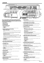
... instruction manual of amplifier B using an RCA cable with a ground lead attached, connect the ground lead to this control according to be connected should have changed ID numbers of amplifiers, turn Off the POWER switch of the Center Unit and turn it to the Center Unit. 9 REMOTE terminals Used to connect to the setting of the amplifier. This unit is compatible with this position and make bridged connections to use them as a high-power monaural amplifier. (The input right signal is not output.) ) HPF (High-Pass Filter) switch...
... instruction manual of amplifier B using an RCA cable with a ground lead attached, connect the ground lead to this control according to be connected should have changed ID numbers of amplifiers, turn Off the POWER switch of the Center Unit and turn it to the Center Unit. 9 REMOTE terminals Used to connect to the setting of the amplifier. This unit is compatible with this position and make bridged connections to use them as a high-power monaural amplifier. (The input right signal is not output.) ) HPF (High-Pass Filter) switch...
Instruction Manual
Page 6
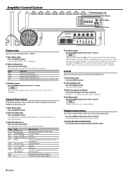
...) T-15 - Then, you have set with the Amplifier Control. NOTE Volume offset value can be initialized. The indicator flashes in the following explains how to cancel the Demonstration mode. 6 English The setup items and set up the display items as follows. To call the Amplifier Control's values, hold down the [2] button 3 or more seconds during ID number display ("AMP"). Indicates the rotation speed of...
...) T-15 - Then, you have set with the Amplifier Control. NOTE Volume offset value can be initialized. The indicator flashes in the following explains how to cancel the Demonstration mode. 6 English The setup items and set up the display items as follows. To call the Amplifier Control's values, hold down the [2] button 3 or more seconds during ID number display ("AMP"). Indicates the rotation speed of...
Instruction Manual
Page 7
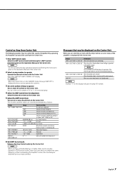
Indicates the current consumption (A). Messages that controlled by the Amplifier Control, the sound may be distorted due to an input overflow. When the speaker output is displayed. NOTE Number "×" on the Operation Manual of the cooling fan in contact with the vehicle ground. Select the "AMP NO"/"AMP CONTROL NO" display. Display Range "VOLT"/"CURR"/"TEMP"/"FAN" "VOLT" "CURR" "TEMP" "FAN" Adjustment Item The amp state...
Indicates the current consumption (A). Messages that controlled by the Amplifier Control, the sound may be distorted due to an input overflow. When the speaker output is displayed. NOTE Number "×" on the Operation Manual of the cooling fan in contact with the vehicle ground. Select the "AMP NO"/"AMP CONTROL NO" display. Display Range "VOLT"/"CURR"/"TEMP"/"FAN" "VOLT" "CURR" "TEMP" "FAN" Adjustment Item The amp state...
Instruction Manual
Page 8
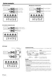
...; High-power 2-channel system L CENTER UNIT LL R AR R LL R BR Left speaker (Bridged) Right speaker (Bridged) 150 100 70 50 200 LPF FREQUENCY(Hz) 100 70 150 2 3 4 50 200 (MIN)5 1 100 0.5 70 0.3 0.2(MAX) 50 150 2 3 4 200 (MIN)5 1 0.5 0.3 0.2(MAX) HPF INPUT HPF INPUT FREQUENCY(Hz) SENSITIVITY(V) FREQUENCY(Hz) SENSITIVITY(V) B ch FILTER HPF AMP CONT ON A ch ISF OPERATION HPF OPERATION ON MONO(Lch) ON MONO(Lch) OFF LPF OFF OFF STEREO OFF STEREO ■ 2-channel + Subwoofer...
...; High-power 2-channel system L CENTER UNIT LL R AR R LL R BR Left speaker (Bridged) Right speaker (Bridged) 150 100 70 50 200 LPF FREQUENCY(Hz) 100 70 150 2 3 4 50 200 (MIN)5 1 100 0.5 70 0.3 0.2(MAX) 50 150 2 3 4 200 (MIN)5 1 0.5 0.3 0.2(MAX) HPF INPUT HPF INPUT FREQUENCY(Hz) SENSITIVITY(V) FREQUENCY(Hz) SENSITIVITY(V) B ch FILTER HPF AMP CONT ON A ch ISF OPERATION HPF OPERATION ON MONO(Lch) ON MONO(Lch) OFF LPF OFF OFF STEREO OFF STEREO ■ 2-channel + Subwoofer...

Instruction Manual
Page 9
...; A speaker wire is being used for possible problems. PROBLEM No sound. (No sound from the Center • The ID number of the Center Unit first, then turn it is too small (or too large). be operated from one side.) (Blown fuse.) POSSIBLE CAUSE • Input (or output) cables are connected with the Amplifier Control. of the terminals and wires well. • Connect the speaker wire again so that it On again. Audio Section Max Power Output ...960 W Rated Power Output...
...; A speaker wire is being used for possible problems. PROBLEM No sound. (No sound from the Center • The ID number of the Center Unit first, then turn it is too small (or too large). be operated from one side.) (Blown fuse.) POSSIBLE CAUSE • Input (or output) cables are connected with the Amplifier Control. of the terminals and wires well. • Connect the speaker wire again so that it On again. Audio Section Max Power Output ...960 W Rated Power Output...


