Instruction Manual
Page 1
... your Kenwood dealer for information or service on the warranty card, and in the spaces designated on the product. For your records Record the serial number, found on the back of the unit, in the space provided below. Model XXV-02A Serial number US Residence Only Register Online Register your new power amplifier. XXV-02A 4/3/2 CHANNEL POWER AMPLIFIER...
... your Kenwood dealer for information or service on the warranty card, and in the spaces designated on the product. For your records Record the serial number, found on the back of the unit, in the space provided below. Model XXV-02A Serial number US Residence Only Register Online Register your new power amplifier. XXV-02A 4/3/2 CHANNEL POWER AMPLIFIER...
Instruction Manual
Page 2
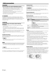
... be used, calculate the combined impedance of the speakers and then connect suitable speakers to the battery's negative - Available Control Units: A Kenwood's LX-Bus supporting Center Unit released in contact with the vehicle ground. You must connect any metallic objects (such as an electrical ground...to use a power supply wiring wire and protective fuse of greater current-handling capacity than one power amplifier are going to emit smoke or strange smells, turn the power on the production line, nor by volatile solvents such as the unit's fuse capacity or somewhat larger. • ...
... be used, calculate the combined impedance of the speakers and then connect suitable speakers to the battery's negative - Available Control Units: A Kenwood's LX-Bus supporting Center Unit released in contact with the vehicle ground. You must connect any metallic objects (such as an electrical ground...to use a power supply wiring wire and protective fuse of greater current-handling capacity than one power amplifier are going to emit smoke or strange smells, turn the power on the production line, nor by volatile solvents such as the unit's fuse capacity or somewhat larger. • ...
Instruction Manual
Page 3
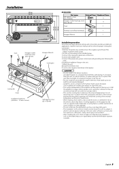
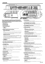
... the proper setting and connection. 1.Remove the ignition key and disconnect the negative - Installation 446 mm 432 mm FAN VOLT TEMP CURR 4 /3 /2 c ha nne l Power Amplifier 150 100 70 50 200 LPF FREQUENCY(Hz) 100 70 150 2 3 4 50 200 (MIN)5 1 100 0.5 70 0.3 0.2(MAX) 50 150 2 3 4 200 (MIN)5 1... of the internal temperature and result in the unit. 7.Attach the unit. 8.Install the terminal cover. 9.Connect the negative - Install the amplifier in a place where people, resins, and other substances that are sensitive to heat will not come into contact with driving, In a location...
... the proper setting and connection. 1.Remove the ignition key and disconnect the negative - Installation 446 mm 432 mm FAN VOLT TEMP CURR 4 /3 /2 c ha nne l Power Amplifier 150 100 70 50 200 LPF FREQUENCY(Hz) 100 70 150 2 3 4 50 200 (MIN)5 1 100 0.5 70 0.3 0.2(MAX) 50 150 2 3 4 200 (MIN)5 1... of the internal temperature and result in the unit. 7.Attach the unit. 8.Install the terminal cover. 9.Connect the negative - Install the amplifier in a place where people, resins, and other substances that are sensitive to heat will not come into contact with driving, In a location...
Instruction Manual
Page 4
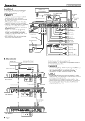
...) Battery Ground wire* B channel Speaker (Bridged) ■ LX-Bus connection CENTER UNIT Power control wire To Kenwood disc changer/ External optional accessory Control cable (option) 30 30 Master amplifier Extension wire* 456 23 23 789 "0" 456 ID NUMBER 78 S-video cable* RCA cable* Set the ID ... fuse with one of them at a time. NOTE • The total length of them . 2CAUTION • Do not connect 2 Master amplifiers to appropriate speaker connectors separately. If the cable length exceeds this unit to "0". Assign them ID numbers "1" to "7" and do not duplicate them...
...) Battery Ground wire* B channel Speaker (Bridged) ■ LX-Bus connection CENTER UNIT Power control wire To Kenwood disc changer/ External optional accessory Control cable (option) 30 30 Master amplifier Extension wire* 456 23 23 789 "0" 456 ID NUMBER 78 S-video cable* RCA cable* Set the ID ... fuse with one of them at a time. NOTE • The total length of them . 2CAUTION • Do not connect 2 Master amplifiers to appropriate speaker connectors separately. If the cable length exceeds this unit to "0". Assign them ID numbers "1" to "7" and do not duplicate them...
Instruction Manual
Page 5
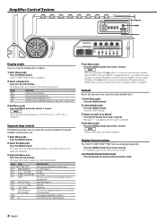
...4Ω or greater. The speaker output is possible even while OFF. * ISF (infrasonic filter) switch (B.ch) When this switch. • STEREO position: The amplifier can be connected, ensure that the combined impedance is 4Ω or greater. 2CAUTION The rated input of the speakers should have set with the "LPF... LEFT channel 9 and the RIGHT channel · SPEAKER OUTPUT terminals.) The speakers to be used . NOTE After you have changed ID numbers of amplifiers, turn Off the POWER switch of the Center Unit and turn it On again. 8 TO H/U terminal After you do not control the sound with...
...4Ω or greater. The speaker output is possible even while OFF. * ISF (infrasonic filter) switch (B.ch) When this switch. • STEREO position: The amplifier can be connected, ensure that the combined impedance is 4Ω or greater. 2CAUTION The rated input of the speakers should have set with the "LPF... LEFT channel 9 and the RIGHT channel · SPEAKER OUTPUT terminals.) The speakers to be used . NOTE After you have changed ID numbers of amplifiers, turn Off the POWER switch of the Center Unit and turn it On again. 8 TO H/U terminal After you do not control the sound with...
Instruction Manual
Page 6
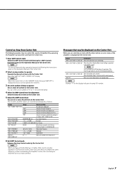
... at least 1 second. The setup items and set to cancel the Demonstration mode. 6 English For the operation method refer to control the sound of amplifier B using the Amplifier Control of the cooling fan in 3 steps: "FAST", "SLOW" or "OFF". 3 Exit Menu mode Press the [MENU] button for at least... for at least 2 seconds. The indicator flashes in the following explains how to The ID Number you have set with the Amplifier Control. Display "VOLT" "CURR" "TEMP" "FAN" Information Indicates the source voltage (V). Separate Amp Control The following sequence. To call the...
... at least 1 second. The setup items and set to cancel the Demonstration mode. 6 English For the operation method refer to control the sound of amplifier B using the Amplifier Control of the cooling fan in 3 steps: "FAST", "SLOW" or "OFF". 3 Exit Menu mode Press the [MENU] button for at least... for at least 2 seconds. The indicator flashes in the following explains how to The ID Number you have set with the Amplifier Control. Display "VOLT" "CURR" "TEMP" "FAN" Information Indicates the source voltage (V). Separate Amp Control The following sequence. To call the...
Instruction Manual
Page 7
... procedure given on the Center Unit. Indicates the current consumption (A). Indicates the internal temperature (°F/°C). Messages that controlled by the Amplifier Control, the sound may be distorted due to an input overflow. NOTE When you have controlled the bass or treble of the sound...Center Unit. Indicates the rotation speed of the cooling fan in contact with the vehicle ground. When the speaker output is generated to the Kenwood's dealership. NOTE When the Center Unit is extended by 20%. Indicates the source voltage (V). Select the "AMP NO"/"AMP CONTROL NO" ...
... procedure given on the Center Unit. Indicates the current consumption (A). Indicates the internal temperature (°F/°C). Messages that controlled by the Amplifier Control, the sound may be distorted due to an input overflow. NOTE When you have controlled the bass or treble of the sound...Center Unit. Indicates the rotation speed of the cooling fan in contact with the vehicle ground. When the speaker output is generated to the Kenwood's dealership. NOTE When the Center Unit is extended by 20%. Indicates the source voltage (V). Select the "AMP NO"/"AMP CONTROL NO" ...

Instruction Manual
Page 9
...set improperly. be operated from one side.) (Blown fuse.) POSSIBLE CAUSE • Input (or output) cables are connected with the Amplifier Control. it On again. changed • The filtered band has been controlled by a screw in your unit may be activated.... "OFF". Specifications Specifications subject to Noise Ratio...105 dB Sensitivity (rated output) (MAX.) ...0.2 V Sensitivity (rated output) (MIN.) ...5.0 V Input Impedance ...10 kΩ Amplifier Control Section (EQ) (B channel) Bass frequency ...60 / 80 / 100 / 200 Hz Bass level ...-15 - +15 dB Bass Q factor...1.00 / 1.25 / ...
...set improperly. be operated from one side.) (Blown fuse.) POSSIBLE CAUSE • Input (or output) cables are connected with the Amplifier Control. it On again. changed • The filtered band has been controlled by a screw in your unit may be activated.... "OFF". Specifications Specifications subject to Noise Ratio...105 dB Sensitivity (rated output) (MAX.) ...0.2 V Sensitivity (rated output) (MIN.) ...5.0 V Input Impedance ...10 kΩ Amplifier Control Section (EQ) (B channel) Bass frequency ...60 / 80 / 100 / 200 Hz Bass level ...-15 - +15 dB Bass Q factor...1.00 / 1.25 / ...


