
User Manual
Page 3
... • Connect the equipment to an outlet on a circuit different from that the interference will function normally. Contact a KENWOOD service station 19 or your transceiver while driving because it is simply 4 too dangerous. 5 • Be aware of local laws pertaining to ... the instructions, may cause harmful interference to which can generate radio frequency energy and, if not installed and used in the instruction manual. When condensation occurs, the microcomputer and/or the transmit/receive circuits may become unstable, resulting in a particular installation. Never use...
... • Connect the equipment to an outlet on a circuit different from that the interference will function normally. Contact a KENWOOD service station 19 or your transceiver while driving because it is simply 4 too dangerous. 5 • Be aware of local laws pertaining to ... the instructions, may cause harmful interference to which can generate radio frequency energy and, if not installed and used in the instruction manual. When condensation occurs, the microcomputer and/or the transmit/receive circuits may become unstable, resulting in a particular installation. Never use...
User Manual
Page 6
...ENTRY (U.S.A./ CANADA ONLY 54 Frequency Entry 54 Memory Channel Number Entry 54 Tone Frequency Number Entry 55 CHANGING FREQUENCY STEP SIZE 55 DISPLAY DIMMER 56 Manual Dimmer Change 56 Auto Dimmer Change 56 BEEP VOLUME CHANGE 56 DISPLAY DEMONSTRATION 56 LOCK 57 Transceiver Lock 57 All Lock 57 POWER-ON MESSAGE...VOICE SYNTHESIZER UNIT 67 INSTALLING A DETACHABLE FRONT PANEL KIT (DFK-3C/ DFK-4C/ DFK-7C 67 Installation Examples 69 CHAPTER 22 MAINTENANCE GENERAL INFORMATION 70 SERVICE 70 SERVICE NOTE 70 CLEANING 70 TROUBLESHOOTING 71 SPECIFICATIONS POWER ON FUNCTIONS SUMMARY INDEX
...ENTRY (U.S.A./ CANADA ONLY 54 Frequency Entry 54 Memory Channel Number Entry 54 Tone Frequency Number Entry 55 CHANGING FREQUENCY STEP SIZE 55 DISPLAY DIMMER 56 Manual Dimmer Change 56 Auto Dimmer Change 56 BEEP VOLUME CHANGE 56 DISPLAY DEMONSTRATION 56 LOCK 57 Transceiver Lock 57 All Lock 57 POWER-ON MESSAGE...VOICE SYNTHESIZER UNIT 67 INSTALLING A DETACHABLE FRONT PANEL KIT (DFK-3C/ DFK-4C/ DFK-7C 67 Installation Examples 69 CHAPTER 22 MAINTENANCE GENERAL INFORMATION 70 SERVICE 70 SERVICE NOTE 70 CLEANING 70 TROUBLESHOOTING 71 SPECIFICATIONS POWER ON FUNCTIONS SUMMARY INDEX
User Manual
Page 71
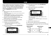
contact a KENWOOD service center. • Data transfer starts. • "SEND" appears. 5 Note: 6 ◆ Before connecting the ...8226; "CLONE" appears. 3 one transceiver is wired as an option (E30-3326-05); The cable for connecting the two TM-G707 6 On the source transceiver, press [CALL]. 4 transceivers is used to copy exactly all transceiver settings to 5 On the...the two transceivers and exactly follow the procedures given in one time. Everything set or stored in this manual. 1 Connect one end of the appropriate cable to the DATA connector of one transceiver. 2 Connect the...
contact a KENWOOD service center. • Data transfer starts. • "SEND" appears. 5 Note: 6 ◆ Before connecting the ...8226; "CLONE" appears. 3 one transceiver is wired as an option (E30-3326-05); The cable for connecting the two TM-G707 6 On the source transceiver, press [CALL]. 4 transceivers is used to copy exactly all transceiver settings to 5 On the...the two transceivers and exactly follow the procedures given in one time. Everything set or stored in this manual. 1 Connect one end of the appropriate cable to the DATA connector of one transceiver. 2 Connect the...