

User Manual
Page 1
INSTRUCTION MANUAL 144/440 MHz FM DUAL BANDER TM-G707A 144/430 MHz FM DUAL BANDER TM-G707A 144/430 MHz FM DUAL BANDER TM-G707E KENWOOD CORPORATION © B62-1509-00 (K,E,M) 09 08 07 06 05 04 03 02 01 00
INSTRUCTION MANUAL 144/440 MHz FM DUAL BANDER TM-G707A 144/430 MHz FM DUAL BANDER TM-G707A 144/430 MHz FM DUAL BANDER TM-G707E KENWOOD CORPORATION © B62-1509-00 (K,E,M) 09 08 07 06 05 04 03 02 01 00
User Manual
Page 2
...programmable with an optional front panel kit, the separated panel can be appreciated by this KENWOOD FM transceiver. TM-G707A: 144/440 MHz FM Dual Bander (U.S.A./ Canada) TM-G707A: 144/430 MHz FM Dual Bander (General market) TM-G707E: 144/430 MHz FM Dual Bander (Europe) FEATURES This transceiver has the ... various data. • Allows each memory channel to be named using the same frequency. • Equipped with an easy-to purchase this manual. you decided to -read large LCD with a transceiver smaller than some single banders. We are using up to use only the basic functions...
...programmable with an optional front panel kit, the separated panel can be appreciated by this KENWOOD FM transceiver. TM-G707A: 144/440 MHz FM Dual Bander (U.S.A./ Canada) TM-G707A: 144/430 MHz FM Dual Bander (General market) TM-G707E: 144/430 MHz FM Dual Bander (Europe) FEATURES This transceiver has the ... various data. • Allows each memory channel to be named using the same frequency. • Equipped with an easy-to purchase this manual. you decided to -read large LCD with a transceiver smaller than some single banders. We are using up to use only the basic functions...
User Manual
Page 3
... may be determined by turning the equipment off and on, the user is encouraged to try to correct the interference by KENWOOD documentation. 12 • Do not expose the transceiver to long periods of 13 direct sunlight nor place the transceiver close to...the transceiver in doubt, do not attempt to provide reasonable protection against harmful interference in the instruction manual. Never use of 6 headphones/headsets while driving on public 7 roads. Contact a KENWOOD service station 19 or your transceiver while driving because it is simply 4 too dangerous. 5 &#...
... may be determined by turning the equipment off and on, the user is encouraged to try to correct the interference by KENWOOD documentation. 12 • Do not expose the transceiver to long periods of 13 direct sunlight nor place the transceiver close to...the transceiver in doubt, do not attempt to provide reasonable protection against harmful interference in the instruction manual. Never use of 6 headphones/headsets while driving on public 7 roads. Contact a KENWOOD service station 19 or your transceiver while driving because it is simply 4 too dangerous. 5 &#...

User Manual
Page 4
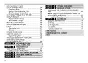
CONTENTS SUPPLIED ACCESSORIES 1 CONVENTIONS FOLLOWED IN THIS MANUAL ....... 1 CHAPTER 1 PREPARATION FOR MOBILE AND FIXED STATION OPERATION MOBILE INSTALLATION 2 Installation Example 2 Installation Steps 2 DC POWER CABLE CONNECTION 3 Mobile Operation 3 Fixed Station Operation 4 Replacing Fuses 5 ...
CONTENTS SUPPLIED ACCESSORIES 1 CONVENTIONS FOLLOWED IN THIS MANUAL ....... 1 CHAPTER 1 PREPARATION FOR MOBILE AND FIXED STATION OPERATION MOBILE INSTALLATION 2 Installation Example 2 Installation Steps 2 DC POWER CABLE CONNECTION 3 Mobile Operation 3 Fixed Station Operation 4 Replacing Fuses 5 ...
User Manual
Page 6
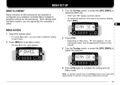
... ENTRY (U.S.A./ CANADA ONLY 54 Frequency Entry 54 Memory Channel Number Entry 54 Tone Frequency Number Entry 55 CHANGING FREQUENCY STEP SIZE 55 DISPLAY DIMMER 56 Manual Dimmer Change 56 Auto Dimmer Change 56 BEEP VOLUME CHANGE 56 DISPLAY DEMONSTRATION 56 LOCK 57 Transceiver Lock 57 All Lock 57 POWER-ON MESSAGE...
... ENTRY (U.S.A./ CANADA ONLY 54 Frequency Entry 54 Memory Channel Number Entry 54 Tone Frequency Number Entry 55 CHANGING FREQUENCY STEP SIZE 55 DISPLAY DIMMER 56 Manual Dimmer Change 56 Auto Dimmer Change 56 BEEP VOLUME CHANGE 56 DISPLAY DEMONSTRATION 56 LOCK 57 Transceiver Lock 57 All Lock 57 POWER-ON MESSAGE...
User Manual
Page 7
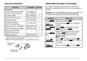
Microphone hanger Microphone hanger screw CONVENTIONS FOLLOWED IN THIS MANUAL The writing conventions described below have been followed to do Press [KEY]. Press Press and hold KEY for 1 second or [KEY] (1 s). With transceiver power OFF,...hanger 2 (U.S.A./ Canada only) J19-1526-XX 1 Screw set (U.S.A./ Canada) 2 N99-0382-XX 1 Screw set (Europe/ General) N99-0331-XX 1 Warranty card (U.S.A./ Canada/ Europe only) - 1 Instruction manual B62-1509-XX 1 1 The MC-53DM and MC-45 microphones are also sold as optional accessories {page 66}. 2 Attach the microphone hanger at an appropriate...
Microphone hanger Microphone hanger screw CONVENTIONS FOLLOWED IN THIS MANUAL The writing conventions described below have been followed to do Press [KEY]. Press Press and hold KEY for 1 second or [KEY] (1 s). With transceiver power OFF,...hanger 2 (U.S.A./ Canada only) J19-1526-XX 1 Screw set (U.S.A./ Canada) 2 N99-0382-XX 1 Screw set (Europe/ General) N99-0331-XX 1 Warranty card (U.S.A./ Canada/ Europe only) - 1 Instruction manual B62-1509-XX 1 1 The MC-53DM and MC-45 microphones are also sold as optional accessories {page 66}. 2 Attach the microphone hanger at an appropriate...

User Manual
Page 13
The time spent will get you on the air in your favorite drink for an hour or two. So, you tend to discard instruction manuals along with the packaging material .....please don't. MC-53DM 1 Switch ON the DC power supply, then 2 press the switch. 3 4 Turn the VOL and SQL controls...Repeat steps and to select a 11 frequency. 12 13 Press and hold Mic [PTT], then speak 14 in your most comfortable operating chair with this manual and your first QSO right away. YOUR FIRST QSO If you can enjoy the exhilaration that comes with opening a brand new transceiver. The 7 steps given...
The time spent will get you on the air in your favorite drink for an hour or two. So, you tend to discard instruction manuals along with the packaging material .....please don't. MC-53DM 1 Switch ON the DC power supply, then 2 press the switch. 3 4 Turn the VOL and SQL controls...Repeat steps and to select a 11 frequency. 12 13 Press and hold Mic [PTT], then speak 14 in your most comfortable operating chair with this manual and your first QSO right away. YOUR FIRST QSO If you can enjoy the exhilaration that comes with opening a brand new transceiver. The 7 steps given...

User Manual
Page 16
... {page 16}. • Memory channels when in 1 MHz steps or 10 MHz steps {page 16}, using the Tuning control or Mic [UP]/ [DWN]. In this manual. 3 4 5 6 7 8 9 10 q CALL button 11 Recalls the Call channel {page 31}. Also provides: 18 • VFO Scan start/stop to scan the entire VFO range 19...
... {page 16}. • Memory channels when in 1 MHz steps or 10 MHz steps {page 16}, using the Tuning control or Mic [UP]/ [DWN]. In this manual. 3 4 5 6 7 8 9 10 q CALL button 11 Recalls the Call channel {page 31}. Also provides: 18 • VFO Scan start/stop to scan the entire VFO range 19...
User Manual
Page 25
... 11 subsequent steps, see the appropriate sections in this transceiver are selected or configured via a software-controlled Menu instead of physical controls on this 12 manual. 13 5 Turn the Tuning control, or press Mic [UP]/ [DWN], to switch the selection. 14 15 16 17 18 19 6 Press [OK] again to complete...
... 11 subsequent steps, see the appropriate sections in this transceiver are selected or configured via a software-controlled Menu instead of physical controls on this 12 manual. 13 5 Turn the Tuning control, or press Mic [UP]/ [DWN], to switch the selection. 14 15 16 17 18 19 6 Press [OK] again to complete...
User Manual
Page 62
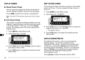
... Menu No. 16 (BEEP). 3 Press [OK], then turn the Tuning 11 control. Press [F]+[ ] to switch the function ON (or OFF). DISPLAY DIMMER 1 2 ■ Manual Dimmer Change 3 You can manually change the display illumination to suit the lighting conditions where you are operating. 4 Press [DIM] to select from levels 1 to 7 and OFF. •...
... Menu No. 16 (BEEP). 3 Press [OK], then turn the Tuning 11 control. Press [F]+[ ] to switch the function ON (or OFF). DISPLAY DIMMER 1 2 ■ Manual Dimmer Change 3 You can manually change the display illumination to suit the lighting conditions where you are operating. 4 Press [DIM] to select from levels 1 to 7 and OFF. •...
User Manual
Page 71
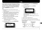
...ERROR" appears on the display, you might have performed incorrect operations. The cable for connecting the two TM-G707 6 On the source transceiver, press [CALL]. 4 transceivers is available as below: 17 DATA...19 DE PKS/RxD 20 PR9 PRI 21 SQC/TxD 22 E (GND) NC: No connection 65 contact a KENWOOD service center. • Data transfer starts. • "SEND" appears. 5 Note: 6 ◆ Before ...at • "CLONE" appears. 3 one time. Everything set or stored in this manual. 1 Connect one end of the appropriate cable to the DATA connector of one transceiver as required....
...ERROR" appears on the display, you might have performed incorrect operations. The cable for connecting the two TM-G707 6 On the source transceiver, press [CALL]. 4 transceivers is available as below: 17 DATA...19 DE PKS/RxD 20 PR9 PRI 21 SQC/TxD 22 E (GND) NC: No connection 65 contact a KENWOOD service center. • Data transfer starts. • "SEND" appears. 5 Note: 6 ◆ Before ...at • "CLONE" appears. 3 one time. Everything set or stored in this manual. 1 Connect one end of the appropriate cable to the DATA connector of one transceiver as required....
User Manual
Page 77
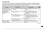
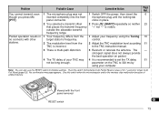
... are usually caused by circuit failure. Black → ( - ). and pressing the 2 One or more of the power cable 2 Look for the cause of this instruction manual, before assuming your transceiver is strange. problems, install a new fuse(s) with the 10 same ratings. 11 3 The front panel was connected 1 Connect the supplied DC...
... are usually caused by circuit failure. Black → ( - ). and pressing the 2 One or more of the power cable 2 Look for the cause of this instruction manual, before assuming your transceiver is strange. problems, install a new fuse(s) with the 10 same ratings. 11 3 The front panel was connected 1 Connect the supplied DC...
User Manual
Page 79
... the microcomputer and/or the memory chip malfunction because of your computer. 14 Note: You can also use the RESET switch to the TNC instruction manual. 9 3 There is incorrect. control. 8 2 Adjust the TNC modulation level according 61 to initialize settings. parameter on packet. 12 4 The TX delay of ambient factors. 16...
... the microcomputer and/or the memory chip malfunction because of your computer. 14 Note: You can also use the RESET switch to the TNC instruction manual. 9 3 There is incorrect. control. 8 2 Adjust the TNC modulation level according 61 to initialize settings. parameter on packet. 12 4 The TX delay of ambient factors. 16...