

Instruction Manual
Page 2
... ...SCANSELECTING A SCAN RESUME METHOD...1 Time-Operate Resume Time ...1 Carrier-Operated Resume Time ...1 VFO SCAN ...2 MEMORY SCAN ...2 Locking Out a Memory Channel...2 GROUP SCAN ...2 Memory Group Link...2 PROGRAM SCAN ...3 Setting Scan Limits...3 Using Program Scan ...3 MHz SCAN ...3 CALL SCAN ...3 VISUAL SCAN...4 Selecting the Number of Channels...4 CONTENTS-1
... ...SCANSELECTING A SCAN RESUME METHOD...1 Time-Operate Resume Time ...1 Carrier-Operated Resume Time ...1 VFO SCAN ...2 MEMORY SCAN ...2 Locking Out a Memory Channel...2 GROUP SCAN ...2 Memory Group Link...2 PROGRAM SCAN ...3 Setting Scan Limits...3 Using Program Scan ...3 MHz SCAN ...3 CALL SCAN ...3 VISUAL SCAN...4 Selecting the Number of Channels...4 CONTENTS-1

Instruction Manual
Page 5
... ...9 Output Type ...9 SETTING WAY POINT ...10 Way Point Format ...10 Way Point Name ...10 Way Point Output ...10 COM PORT ON/OFF...10 Output ...10 PROGRAMMING POSITION DATA...10 Select Position channel ...10 Name Entry ...10 Latitude Entry ...10 Longitude Entry ...10 SETTING BEACON INFORMATION ...10 Speed Information ...10 Altitude Information...
... ...9 Output Type ...9 SETTING WAY POINT ...10 Way Point Format ...10 Way Point Name ...10 Way Point Output ...10 COM PORT ON/OFF...10 Output ...10 PROGRAMMING POSITION DATA...10 Select Position channel ...10 Name Entry ...10 Latitude Entry ...10 Longitude Entry ...10 SETTING BEACON INFORMATION ...10 Speed Information ...10 Altitude Information...

Instruction Manual
Page 6
... UICHECK ...16 UIDIGI ...16 UIFLOOD ...17 UITRACE...17 STORING USER PHRASES ...17 STORING AUTO MESSAGE REPLY...18 Auto Answer Reply ...18 Reply To Callsign ...18 PROGRAMMING A MESSAGE GROUP CODE ...18 SETTING SOUND...19 RX Beep Type ...19 TX Beep ...19 Special Call Sound ...19 APRS Voice Announce ...19 SETTING INTERRUPT DISPLAY... ...20 Slow rate ...20 Fast rate ...20 Turn angle ...20 Turn slope ...20 Turn time ...20 PACKET MONITOR DISPLAY ...21 DX PACKETCLUSTERS MONITOR...22 Connecting TM-D710G with the HF Transceiver ...22 CONTENTS-5
... UICHECK ...16 UIDIGI ...16 UIFLOOD ...17 UITRACE...17 STORING USER PHRASES ...17 STORING AUTO MESSAGE REPLY...18 Auto Answer Reply ...18 Reply To Callsign ...18 PROGRAMMING A MESSAGE GROUP CODE ...18 SETTING SOUND...19 RX Beep Type ...19 TX Beep ...19 Special Call Sound ...19 APRS Voice Announce ...19 SETTING INTERRUPT DISPLAY... ...20 Slow rate ...20 Fast rate ...20 Turn angle ...20 Turn slope ...20 Turn time ...20 PACKET MONITOR DISPLAY ...21 DX PACKETCLUSTERS MONITOR...22 Connecting TM-D710G with the HF Transceiver ...22 CONTENTS-5

Instruction Manual
Page 7
... ...1 REPEATER ID TX ...1 Entering your Repeater ID...1 WIRELESS OPERATION (TM-D710GA ONLY WIRELESS OPPREPARATION...1 CONTROL OPERATION ...1 WEATHER ALERT (TM-D710GA ONLY) ...WXWEATHER ALERT ON/ OFF...1 Weather Channel ...1 WEATHER ALERT SCAN ...1 SKY COMMAND SYSTEM II ...SKY CMDCONNECTING THE TRANSPORTER WITH THE HF TRANSCEIVER 1 PREPARATION FLOW ...2 PROGRAMMING CALLSIGNS ...3 PROGRAMMING A TONE FREQUENCY ...3 CONTROL OPERATION ...3 "WIRELESS OPERATION" function is unavailable...
... ...1 REPEATER ID TX ...1 Entering your Repeater ID...1 WIRELESS OPERATION (TM-D710GA ONLY WIRELESS OPPREPARATION...1 CONTROL OPERATION ...1 WEATHER ALERT (TM-D710GA ONLY) ...WXWEATHER ALERT ON/ OFF...1 Weather Channel ...1 WEATHER ALERT SCAN ...1 SKY COMMAND SYSTEM II ...SKY CMDCONNECTING THE TRANSPORTER WITH THE HF TRANSCEIVER 1 PREPARATION FLOW ...2 PROGRAMMING CALLSIGNS ...3 PROGRAMMING A TONE FREQUENCY ...3 CONTROL OPERATION ...3 "WIRELESS OPERATION" function is unavailable...

Instruction Manual
Page 10
... frequency is ON. ◆ You cannot switch Reverse ON or OFF while transmitting. Note: While remaining in place of signals you do not want to program the identified frequency. • While direct contact is ON, the icon will begin blinking. • To exit ASC, press [REV]. Note:...the built-in the transmit mode for a certain period of a repeater, the icon will appear on the display. 3 Press the Tuning control to program the identified frequency in the transmit mode, the transceiver does not continuously transmit a 1750 Hz tone. TONE FREQUENCY ID This function scans ...
... frequency is ON. ◆ You cannot switch Reverse ON or OFF while transmitting. Note: While remaining in place of signals you do not want to program the identified frequency. • While direct contact is ON, the icon will begin blinking. • To exit ASC, press [REV]. Note:...the built-in the transmit mode for a certain period of a repeater, the icon will appear on the display. 3 Press the Tuning control to program the identified frequency in the transmit mode, the transceiver does not continuously transmit a 1750 Hz tone. TONE FREQUENCY ID This function scans ...

Instruction Manual
Page 11
.... 3 Set up any frequency and related data that you will recall often. A total of in mind. MEMORY CHANNELS In Memory channels, you can quickly recall a programmed channel by simple operation. Then you need not reprogram the data every time.
.... 3 Set up any frequency and related data that you will recall often. A total of in mind. MEMORY CHANNELS In Memory channels, you can quickly recall a programmed channel by simple operation. Then you need not reprogram the data every time.

Instruction Manual
Page 12
You may want to recall all programmed memory channels. • When the recalled memory channel is an AM channel, you to dedicate the Call channel as the Call channel instead of "STORING ...
You may want to recall all programmed memory channels. • When the recalled memory channel is an AM channel, you to dedicate the Call channel as the Call channel instead of "STORING ...
Instruction Manual
Page 15
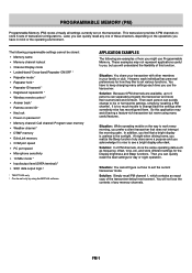
...channel/ Call channel/ Program scan memory • Weather channel 1 • DTMF memory • EchoLink memory • COM port speed • PC port speed • Microphone sensitivity • 10 MHz mode 2 • Input/output level (DATA terminal) 2 • SQC data output logic 2 1 TM-D710GA only 2 Can be... programmable settings cannot be set only by recalling a PM channel. However, each person can separately program the transceiver and store their customized environment. These examples may avoid having a feature-rich transceiver but you might use the transceiver...
...channel/ Call channel/ Program scan memory • Weather channel 1 • DTMF memory • EchoLink memory • COM port speed • PC port speed • Microphone sensitivity • 10 MHz mode 2 • Input/output level (DATA terminal) 2 • SQC data output logic 2 1 TM-D710GA only 2 Can be... programmable settings cannot be set only by recalling a PM channel. However, each person can separately program the transceiver and store their customized environment. These examples may avoid having a feature-rich transceiver but you might use the transceiver...

Instruction Manual
Page 17
...busy frequency or Memory channel until the signal drops out. Becoming comfortable with all types of scans: Scan Type VFO Scan Memory Scan Group Scan Program Scan MHz Scan Call Scan Scan Range Scans all frequencies stored in the Memory channels which resume mode you selected. ◆ When using S-...~ 10 sec. It then continues scanning according to which belong to temporarily stop immediately. ◆ While using Scan. Scans all frequencies within the programmed range, on a non TX band. ◆ Starting Scan switches the Automatic Simplex Checker OFF. SCAN-1
...busy frequency or Memory channel until the signal drops out. Becoming comfortable with all types of scans: Scan Type VFO Scan Memory Scan Group Scan Program Scan MHz Scan Call Scan Scan Range Scans all frequencies stored in the Memory channels which resume mode you selected. ◆ When using S-...~ 10 sec. It then continues scanning according to which belong to temporarily stop immediately. ◆ While using Scan. Scans all frequencies within the programmed range, on a non TX band. ◆ Starting Scan switches the Automatic Simplex Checker OFF. SCAN-1

Instruction Manual
Page 18
.... • To reverse the scan direction, turn the Tuning control clockwise (upward scan) or counterclockwise (downward scan). VFO SCAN VFO Scan monitors all Memory channels programmed with frequency data. 1 Select your desired band. 2 Press [MR] (1s). • Scan starts at the current channel. • The 1 MHz decimal blinks while scanning is...
.... • To reverse the scan direction, turn the Tuning control clockwise (upward scan) or counterclockwise (downward scan). VFO SCAN VFO Scan monitors all Memory channels programmed with frequency data. 1 Select your desired band. 2 Press [MR] (1s). • Scan starts at the current channel. • The 1 MHz decimal blinks while scanning is...

Instruction Manual
Page 19
...again. MHz SCAN MHz Scan monitors a 1 MHz segment of scan. Note: ◆ The lower limit must be selected on the same band. ■ Using Program Scan 1 Select your desired band. 2 Press [VFO]. 3 Rotate the Tuning control to select a frequency within your desired 1 MHz range. 4 Press and ...• To confirm the stored scan limits, press [MR], then select the L and U channels. The current 1 MHz digit determines the limits of Program Scan. ◆ If the current VFO frequency is within your desired scan range. 4 Press [VFO] (1s). • Scan starts at the current frequency....
...again. MHz SCAN MHz Scan monitors a 1 MHz segment of scan. Note: ◆ The lower limit must be selected on the same band. ■ Using Program Scan 1 Select your desired band. 2 Press [VFO]. 3 Rotate the Tuning control to select a frequency within your desired 1 MHz range. 4 Press and ...• To confirm the stored scan limits, press [MR], then select the L and U channels. The current 1 MHz digit determines the limits of Program Scan. ◆ If the current VFO frequency is within your desired scan range. 4 Press [VFO] (1s). • Scan starts at the current frequency....

Instruction Manual
Page 20
... frequency will be used as the center frequency. ◆ If the frequency range specified for Program Scan or Program VFO is narrower than the range specified for Visual Scan, the range for Program Scan or VFO will be used for each channel, that represent 7 S-meter levels (3 segments per level...
... frequency will be used as the center frequency. ◆ If the frequency range specified for Program Scan or Program VFO is narrower than the range specified for Visual Scan, the range for Program Scan or VFO will be used for each channel, that represent 7 S-meter levels (3 segments per level...

Instruction Manual
Page 21
... is ON. • Tone ( ) ➡ CTCSS ( ) ➡ DCS ( ) ➡ Cross Tone ( : default) ➡ Off (no longer appears on the display and blinks. 4 Press the key programmed as [ENTER]. 5 Enter a frequency reference number (01 ~ 42) using the same frequency.
... is ON. • Tone ( ) ➡ CTCSS ( ) ➡ DCS ( ) ➡ Cross Tone ( : default) ➡ Off (no longer appears on the display and blinks. 4 Press the key programmed as [ENTER]. 5 Enter a frequency reference number (01 ~ 42) using the same frequency.

Instruction Manual
Page 22
...when a signal is received. You may find this useful when you are using the microphone: 1 Select your desired band. 2 Press [TONE] 3 times to program the identified frequency in place of [TONE] changes the selection as follows: Tone ( ) ➡ CTCSS ( ) ➡ DCS ( ) ➡... [PTT], then speak into the microphone. • To cancel DCS, press [TONE] until CT no longer appears on the display and blinks. 4 Press the key programmed as follows: Tone ( ) ➡ CTCSS ( ) ➡ DCS ( ) ➡ Cross Tone ( : default) ➡ Off (no display). 3 Press [F], ...
...when a signal is received. You may find this useful when you are using the microphone: 1 Select your desired band. 2 Press [TONE] 3 times to program the identified frequency in place of [TONE] changes the selection as follows: Tone ( ) ➡ CTCSS ( ) ➡ DCS ( ) ➡... [PTT], then speak into the microphone. • To cancel DCS, press [TONE] until CT no longer appears on the display and blinks. 4 Press the key programmed as follows: Tone ( ) ➡ CTCSS ( ) ➡ DCS ( ) ➡ Cross Tone ( : default) ➡ Off (no display). 3 Press [F], ...

Instruction Manual
Page 23
...; When a DCS code is received. To cancel DCS, press [TONE] until DCS no longer appears on the display and blinks. 3 Press the Tuning control to program the identified code in your group are using the microphone keypad. • Refer to the table below for when you access a repeater that... on the display when the Cross Tone function is blinking, to resume scanning. You may find it useful when you do not want to program the identified code. • Rotate the Tuning control while an identified code is On. • Each press of the currently set...
...; When a DCS code is received. To cancel DCS, press [TONE] until DCS no longer appears on the display and blinks. 3 Press the Tuning control to program the identified code in your group are using the microphone keypad. • Refer to the table below for when you access a repeater that... on the display when the Cross Tone function is blinking, to resume scanning. You may find it useful when you do not want to program the identified code. • Rotate the Tuning control while an identified code is On. • Each press of the currently set...

Instruction Manual
Page 26
...control. • The last called EchoLink DTMF Memory channel name and number appears on their website and download the EchoLink software program (free of the control command, etc., are 10 dedicated EchoLink DTMF Memory channels available. EchoLink allows you must register using VoIP... (voice-over the internet, using your communications capabilities. The EchoLink software program allows worldwide connections to be made between stations, or from EL0 ~ EL9. 3 Press the Tuning control to set the selected channel...
...control. • The last called EchoLink DTMF Memory channel name and number appears on their website and download the EchoLink software program (free of the control command, etc., are 10 dedicated EchoLink DTMF Memory channels available. EchoLink allows you must register using VoIP... (voice-over the internet, using your communications capabilities. The EchoLink software program allows worldwide connections to be made between stations, or from EL0 ~ EL9. 3 Press the Tuning control to set the selected channel...

Instruction Manual
Page 28
... and makes it to exit. OTHER OPERATIONS SELECTING AN OUTPUT POWER It is a good idea to select high (H), medium (M), or low (L) power. • You can program different power settings for the maximum time duration according to lower transmit output power. This lowers the risk of the beep. 1 Enter Menu mode and...
... and makes it to exit. OTHER OPERATIONS SELECTING AN OUTPUT POWER It is a good idea to select high (H), medium (M), or low (L) power. • You can program different power settings for the maximum time duration according to lower transmit output power. This lowers the risk of the beep. 1 Enter Menu mode and...
Instruction Manual
Page 29
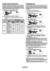
... 144.000 MHz to 145.995 MHz. 1 Select your desired upper frequency limit, then press the Tuning control to exit Menu mode. Note: You cannot program the 100 kHz and subsequent digits. The default on the mode selected. B x A B A, B - - For example, if 144.995 MHz is essential in selecting...SP2 A, B - - EXTERNAL SPEAKER CONFIGURATION This transceiver has two speaker jacks for configurations based on the 430/440 MHz band is 5 kHz (TM-D710GA) or 12.5 kHz (TM-D710GE). OTHER OP-2 Note: Changing between step sizes may correct the displayed frequency. x A, B -
... 144.000 MHz to 145.995 MHz. 1 Select your desired upper frequency limit, then press the Tuning control to exit Menu mode. Note: You cannot program the 100 kHz and subsequent digits. The default on the mode selected. B x A B A, B - - For example, if 144.995 MHz is essential in selecting...SP2 A, B - - EXTERNAL SPEAKER CONFIGURATION This transceiver has two speaker jacks for configurations based on the 430/440 MHz band is 5 kHz (TM-D710GA) or 12.5 kHz (TM-D710GE). OTHER OP-2 Note: Changing between step sizes may correct the displayed frequency. x A, B -

Instruction Manual
Page 31
When TOT times out (default is sometimes necessary or desirable to restrict a single transmission to a specific maximum time. You can program your desired message. • Press [CLR] to HIGH, MEDIUM or LOW. Adjust the contrast as necessary. ■ Positive/ Negative Reversal You can be affected by a ...
When TOT times out (default is sometimes necessary or desirable to restrict a single transmission to a specific maximum time. You can program your desired message. • Press [CLR] to HIGH, MEDIUM or LOW. Adjust the contrast as necessary. ■ Positive/ Negative Reversal You can be affected by a ...

Instruction Manual
Page 32
...)/ MUTE (Speaker Mute)/ SHIFT (Shift)/ DUAL (Dual Mode)/ M>V (Memory to select band A or B, then press [VFO] or [CALL]. 2 Press the key programmed as [ENTER]. 1 Press the left or right [BAND SEL] to VFO Copy)/ 1750 (1750 Hz Tone). ■ Microphone Keys There are 2 PF (Programmable Function)...new value. One of the digits will remain unchanged if you need to enter your desired function for the key. You can still be programmed as [ENTER]. • The Direct Frequency Entry display appears. 2 Set your transceiver settings will leave the remaining digits at their previous values...
...)/ MUTE (Speaker Mute)/ SHIFT (Shift)/ DUAL (Dual Mode)/ M>V (Memory to select band A or B, then press [VFO] or [CALL]. 2 Press the key programmed as [ENTER]. 1 Press the left or right [BAND SEL] to VFO Copy)/ 1750 (1750 Hz Tone). ■ Microphone Keys There are 2 PF (Programmable Function)...new value. One of the digits will remain unchanged if you need to enter your desired function for the key. You can still be programmed as [ENTER]. • The Direct Frequency Entry display appears. 2 Set your transceiver settings will leave the remaining digits at their previous values...