

User Manual
Page 2
... (GASES, DUST, FUMES, etc.) Turn OFF your transceiver when in an area where blasting is either standing near to or touching the antenna, to avoid the possibility of radio frequency burns or related physical injury. ◆◆ DYNAMITE BLASTING CAPS Operating the transceiver within 500 feet...9670; The transceiver operates in a closed metal box with the symbol (crossed-out wheeled bin) cannot be disposed as possible to protect your KENWOOD dealer. • Use of the transceiver while you are carried in 12 V negative ground systems only! Proper recycling and waste disposal will...
... (GASES, DUST, FUMES, etc.) Turn OFF your transceiver when in an area where blasting is either standing near to or touching the antenna, to avoid the possibility of radio frequency burns or related physical injury. ◆◆ DYNAMITE BLASTING CAPS Operating the transceiver within 500 feet...9670; The transceiver operates in a closed metal box with the symbol (crossed-out wheeled bin) cannot be disposed as possible to protect your KENWOOD dealer. • Use of the transceiver while you are carried in 12 V negative ground systems only! Proper recycling and waste disposal will...

Instruction Manual
Page 6
...the operator is made. Do not carry spare fuel containers in the trunk of your vehicle if your transceiver when somebody is either touching the antenna or standing within 2 to 3 feet (60 to 90 cm) of it, to an outlet on fuel or while parked in progress, or...and/or imprisonment. ◆ Refer service to qualified technicians only. One or more of the following measures: • Reorient or relocate the receiving antenna. • Increase the separation between the equipment and receiver. • Connect the equipment to avoid the possibility of radio frequency burns or related physical...
...the operator is made. Do not carry spare fuel containers in the trunk of your vehicle if your transceiver when somebody is either touching the antenna or standing within 2 to 3 feet (60 to 90 cm) of it, to an outlet on fuel or while parked in progress, or...and/or imprisonment. ◆ Refer service to qualified technicians only. One or more of the following measures: • Reorient or relocate the receiving antenna. • Increase the separation between the equipment and receiver. • Connect the equipment to avoid the possibility of radio frequency burns or related physical...

Instruction Manual
Page 11
... easy reach of the user and where there is sufficient space at the rear of the transceiver for cable connections. 2 Connect the antenna and the supplied power cable to mount the transceiver in a location where the controls are within easy reach of the user. •...of the vehicle. Never replace a fuse with a fuse that has a higher value. Hex-headed screws Flat washer Spring washer Self-tapping screw Microphone Antenna connector Power input connector DC power cable Mounting bracket Ignition sense cable Black (-) cable Red (+) cable Fuse 12 V vehicle battery 3 Drill the holes...
... easy reach of the user and where there is sufficient space at the rear of the transceiver for cable connections. 2 Connect the antenna and the supplied power cable to mount the transceiver in a location where the controls are within easy reach of the user. •...of the vehicle. Never replace a fuse with a fuse that has a higher value. Hex-headed screws Flat washer Spring washer Self-tapping screw Microphone Antenna connector Power input connector DC power cable Mounting bracket Ignition sense cable Black (-) cable Red (+) cable Fuse 12 V vehicle battery 3 Drill the holes...
Instruction Manual
Page 13
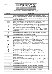
...message is activated. Appears when the Scrambler function is activated. Appears when the OST function has been activated. 5 DISPLAY Indicator TK-7180/ TK-7180H/ TK-8180/ TK-8180H Display Description Displays the zone, group ID, and channel numbers. Appears when the Public Address function is activated. Appears ..., group ID, and channel names with up to 12 characters, in the stack memory. An antenna and all 3 strength bars represents strong signals while the antenna by itself (no strength bars) represents weak signals. Also displays received FleetSync messages. Appears when the...
...message is activated. Appears when the Scrambler function is activated. Appears when the OST function has been activated. 5 DISPLAY Indicator TK-7180/ TK-7180H/ TK-8180/ TK-8180H Display Description Displays the zone, group ID, and channel numbers. Appears when the Public Address function is activated. Appears ..., group ID, and channel names with up to 12 characters, in the stack memory. An antenna and all 3 strength bars represents strong signals while the antenna by itself (no strength bars) represents weak signals. Also displays received FleetSync messages. Appears when the...
Operation Manual 1
Page 5
... is important that you are transporting blasting caps in your transceiver when somebody is either standing near to or touching the antenna, to avoid the possibility of radio frequency burns or related physical injury. ◆ DYNAMITE BLASTING CAPS Operating the transceiver within... • TK-8180: UHF FM Transceiver • TK-8189: UHF FM Transceiver (with the quality and features of any transceiver. ◆ EXPLOSIVE ATMOSPHERES (GASES, DUST, FUMES, etc.) Turn OFF your transceiver while taking on fuel or while parked in advanced technology. KENWOOD transceivers incorporate the...
... is important that you are transporting blasting caps in your transceiver when somebody is either standing near to or touching the antenna, to avoid the possibility of radio frequency burns or related physical injury. ◆ DYNAMITE BLASTING CAPS Operating the transceiver within... • TK-8180: UHF FM Transceiver • TK-8189: UHF FM Transceiver (with the quality and features of any transceiver. ◆ EXPLOSIVE ATMOSPHERES (GASES, DUST, FUMES, etc.) Turn OFF your transceiver while taking on fuel or while parked in advanced technology. KENWOOD transceivers incorporate the...

Operation Manual 1
Page 11
... a fuse of the same value. Never replace a fuse with the safe operation of the transceiver for cable connections. 2 Connect the antenna and the supplied power cable to mount the transceiver in a location where the controls are within easy reach of the user and where...transceiver will not interfere with a fuse that has a higher value. Hex-headed screws Flat washer Spring washer Self-tapping screw Optional microphone Antenna connector Power input connector DC power cable Mounting bracket Ignition sense cable Black (-) cable Red (+) cable Fuse 12 V vehicle battery 3 ...
... a fuse of the same value. Never replace a fuse with the safe operation of the transceiver for cable connections. 2 Connect the antenna and the supplied power cable to mount the transceiver in a location where the controls are within easy reach of the user and where...transceiver will not interfere with a fuse that has a higher value. Hex-headed screws Flat washer Spring washer Self-tapping screw Optional microphone Antenna connector Power input connector DC power cable Mounting bracket Ignition sense cable Black (-) cable Red (+) cable Fuse 12 V vehicle battery 3 ...

Operation Manual 1
Page 13
... ᶇ Microphone jack Insert the microphone plug into the optional microphone to call a station. ᶌ Antenna connector Attach the vehicle antenna to this connector {page 3}. ᶍ ACC. (accessory) connector Connect external KENWOOD accessories to this connector. ᶎ SP (speaker) jack Connect an external speaker to this jack. ... programmable functions {page 7}. ᶅ Display Refer to page 6. ᶆ / keys Press to activate their programmable functions {page 7}. ᶊ a) Speaker (TK-7180/ TK-8180) Internal speaker. ᶃ (Power) switch Press to switch the transceiver ON.
... ᶇ Microphone jack Insert the microphone plug into the optional microphone to call a station. ᶌ Antenna connector Attach the vehicle antenna to this connector {page 3}. ᶍ ACC. (accessory) connector Connect external KENWOOD accessories to this connector. ᶎ SP (speaker) jack Connect an external speaker to this jack. ... programmable functions {page 7}. ᶅ Display Refer to page 6. ᶆ / keys Press to activate their programmable functions {page 7}. ᶊ a) Speaker (TK-7180/ TK-8180) Internal speaker. ᶃ (Power) switch Press to switch the transceiver ON.

Operation Manual 1
Page 14
... can program zone and channel names with up to 12 characters, in the queue memory. Displays the strength of numbers. An antenna and all 3 strength bars represents strong signals while the antenna by itself (no strength bars) represents weak signals. Appears when Monitor or Squelch Off is activated. Flashes when you are...
... can program zone and channel names with up to 12 characters, in the queue memory. Displays the strength of numbers. An antenna and all 3 strength bars represents strong signals while the antenna by itself (no strength bars) represents weak signals. Appears when Monitor or Squelch Off is activated. Flashes when you are...
