
Instruction Manual
Page 2
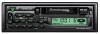
... (CRSC 9 Cassette player features Playing Cassette Tapes 10 Fast Forwarding and Rewinding Cassette Tapes 10 Tuner Call 11 Installation Accessories 12 Installation Procedure 12 Connecting Wires to Terminals 13 Installation 14 Troubleshooting guide 16 Specifications 17 -2-
... (CRSC 9 Cassette player features Playing Cassette Tapes 10 Fast Forwarding and Rewinding Cassette Tapes 10 Tuner Call 11 Installation Accessories 12 Installation Procedure 12 Connecting Wires to Terminals 13 Installation 14 Troubleshooting guide 16 Specifications 17 -2-
Instruction Manual
Page 3
...or clothing, wash it off with the prescribed rating. Use only the screws provided. If you use automotivegrade wires or other wires with a 0.75mm2 (AWG18) or more to prevent wire deterioration and damage to the wire coating. • To prevent a short circuit, never put or leave any metallic objects (such as ... of place when jolted. • When extending the ignition, battery, or ground wires, make sure to use the wrong screws, you could damage the unit. - 3- If the liquid crystal fluid from the LCD contacts your Kenwood dealer. • Be careful not to drop the unit or subject it is ...
...or clothing, wash it off with the prescribed rating. Use only the screws provided. If you use automotivegrade wires or other wires with a 0.75mm2 (AWG18) or more to prevent wire deterioration and damage to the wire coating. • To prevent a short circuit, never put or leave any metallic objects (such as ... of place when jolted. • When extending the ignition, battery, or ground wires, make sure to use the wrong screws, you could damage the unit. - 3- If the liquid crystal fluid from the LCD contacts your Kenwood dealer. • Be careful not to drop the unit or subject it is ...
Instruction Manual
Page 12
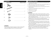
... a short circuit, do not remove the caps on the car or anything else conducting electricity. Make the proper input and output wire connections for those provided might result in the car. • After the unit is installed, check whether the brake lamps, blinkers... above. To prevent a short circuit, remove the key from the ignition and disconnect the - Connect the speaker wires of the wiring harness. 4. Reconnect the - Installation Procedure 1. battery. 8. wires or ground them to any accessories except for each unit. 3. Install the unit in the following order: ground,...
... a short circuit, do not remove the caps on the car or anything else conducting electricity. Make the proper input and output wire connections for those provided might result in the car. • After the unit is installed, check whether the brake lamps, blinkers... above. To prevent a short circuit, remove the key from the ignition and disconnect the - Connect the speaker wires of the wiring harness. 4. Reconnect the - Installation Procedure 1. battery. 8. wires or ground them to any accessories except for each unit. 3. Install the unit in the following order: ground,...
Instruction Manual
Page 13
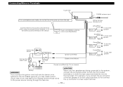
...). White/Black FRONT • L White Gray/Black FRONT • R Gray To front left speaker To front right speaker Ignition key switch ACC Ignition wire (Red) Green/Black REAR • L Green Purple/Black REAR • R Purple To rear left speaker To rear right speaker Car fuse box (...Main fuse) Car fuse box Battery wire (Yellow) Ground wire (Black) · (To car chassis) + - 2CAUTION Battery 2WARNING If you connect the ignition wire (red) and the battery wire (yellow) to the car chassis (ground), you connect the + connector of the...
...). White/Black FRONT • L White Gray/Black FRONT • R Gray To front left speaker To front right speaker Ignition key switch ACC Ignition wire (Red) Green/Black REAR • L Green Purple/Black REAR • R Purple To rear left speaker To rear right speaker Car fuse box (...Main fuse) Car fuse box Battery wire (Yellow) Ground wire (Black) · (To car chassis) + - 2CAUTION Battery 2WARNING If you connect the ignition wire (red) and the battery wire (yellow) to the car chassis (ground), you connect the + connector of the...
Instruction Manual
Page 16
... mode Nothing happens when the buttons are connected incorrectly. The memory is erased when the ignition is connected to Terminals". The input/output wires or wiring harness are pressed. SOLUTION After checking for possible problems. PROBLEM The power does not turn on "Cleaning the tape head" (see p....each output terminal is turned off Attenuator. The fader or balance settings are set all the way. Press the reset button on "Connecting Wires to Terminals". - 16 - One of slight misoperation or miswiring. The tape has not been inserted correctly in the unit is being ...
... mode Nothing happens when the buttons are connected incorrectly. The memory is erased when the ignition is connected to Terminals". The input/output wires or wiring harness are pressed. SOLUTION After checking for possible problems. PROBLEM The power does not turn on "Cleaning the tape head" (see p....each output terminal is turned off Attenuator. The fader or balance settings are set all the way. Press the reset button on "Connecting Wires to Terminals". - 16 - One of slight misoperation or miswiring. The tape has not been inserted correctly in the unit is being ...


