
User Manual
Page 21
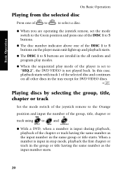
... player main unit lights up and playback starts. ¶ The DISC 1 to 5 buttons are operating the joystick remote, set the mode switch to the Green position and press one of the DISC 1 to 5 buttons. ¶ The disc number indicator above one of the DISC 1 to 5 buttons on all random and program play modes. ¶ When the sequential play mode of the player is set to 9 and +10 . REPEAT MENU A-B REPEAT ¶ With a DVD, when a number is input...
... player main unit lights up and playback starts. ¶ The DISC 1 to 5 buttons are operating the joystick remote, set the mode switch to the Green position and press one of the DISC 1 to 5 buttons. ¶ The disc number indicator above one of the DISC 1 to 5 buttons on all random and program play modes. ¶ When the sequential play mode of the player is set to 9 and +10 . REPEAT MENU A-B REPEAT ¶ With a DVD, when a number is input...
User Manual
Page 24
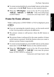
... for the same number of times as the button is pressed. Basic Operation On Basic Operation ¶ To restart normal playback, press the 3 button on the player main unit or the 3 PLAY button on the joystick remote. ¶ When the "IPB Display" is set to On, the TV screen shows "Still (I )", "Still (P)" or "Still (B)" with every still picture of DVD VIDEO. Connection and Setup Guide ¢ Frame-by...
... for the same number of times as the button is pressed. Basic Operation On Basic Operation ¶ To restart normal playback, press the 3 button on the player main unit or the 3 PLAY button on the joystick remote. ¶ When the "IPB Display" is set to On, the TV screen shows "Still (I )", "Still (P)" or "Still (B)" with every still picture of DVD VIDEO. Connection and Setup Guide ¢ Frame-by...
User Manual
Page 86
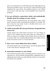
... purchase new cables at most common home entertainment problem: no sound from it to double-check your connections for each device. 4. User error is working. First check the manual when something doesn't work how you may find the solution to the other devices' manuals as well? This step will really help narrow down the possible causes. Use the Connection and Setup Guide to . For one connected to operate the player. Instruction manuals are...
... purchase new cables at most common home entertainment problem: no sound from it to double-check your connections for each device. 4. User error is working. First check the manual when something doesn't work how you may find the solution to the other devices' manuals as well? This step will really help narrow down the possible causes. Use the Connection and Setup Guide to . For one connected to operate the player. Instruction manuals are...
User Manual
Page 88
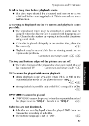
... takes long time before starting playback. A warning is set to "Off". Œ DVF-R9030 87 Connection and Setup Guide 8 Troubleshooting VCD cannot be unavailable due to "SEQ.2". Connection and Setup Guide 6* The top and bottom edges of the picture are not displayed when the played DVD does not contain the recording of the connected TV. Switch it in the radial directions using a soft cloth. ¶ If the disc is...
... takes long time before starting playback. A warning is set to "Off". Œ DVF-R9030 87 Connection and Setup Guide 8 Troubleshooting VCD cannot be unavailable due to "SEQ.2". Connection and Setup Guide 6* The top and bottom edges of the picture are not displayed when the played DVD does not contain the recording of the connected TV. Switch it in the radial directions using a soft cloth. ¶ If the disc is...
User Manual
Page 89
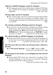
... unit, press the POWER button. Connection and Setup Guide £ The messages in the menus are not displayed in part where no angle is set by the user, the priority language specified for the disc will be selected. Connection and Setup Guide › Troubleshooting 88 DVF-R9030 Symptoms and Treatment Audio (or subtitle) language cannot be changed. ¶ The language cannot be switched when the played DVD does not contain...
... unit, press the POWER button. Connection and Setup Guide £ The messages in the menus are not displayed in part where no angle is set by the user, the priority language specified for the disc will be selected. Connection and Setup Guide › Troubleshooting 88 DVF-R9030 Symptoms and Treatment Audio (or subtitle) language cannot be changed. ¶ The language cannot be switched when the played DVD does not contain...
User Manual
Page 91
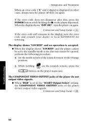
... be set in the display, note the error code and consult your dealer or local KENWOOD for servicing. If the error code does not disappear after this, press the POWER button while holding 7 on the joystick remote, press the P.AUDIO AUDIO 7 button on the player depressed. Connection and Setup Guide 9 If the error code still remains in the "SCART Output Select" setting, the COMPONENT VIDEO OUTPUT jacks of the joystick remote to the standby mode or the disc tray cannot be opened...
... be set in the display, note the error code and consult your dealer or local KENWOOD for servicing. If the error code does not disappear after this, press the POWER button while holding 7 on the joystick remote, press the P.AUDIO AUDIO 7 button on the player depressed. Connection and Setup Guide 9 If the error code still remains in the "SCART Output Select" setting, the COMPONENT VIDEO OUTPUT jacks of the joystick remote to the standby mode or the disc tray cannot be opened...

User Manual 1
Page 2
... United Kingdom Factory fitted moulded mains plug 1. For replacement, use only a 13-Amp ASTA-approved (BS1362) fuse. 2. CAUTION RISK OF ELECTRIC SHOCK DO NOT OPEN CAUTION: TO REDUCE THE RISK OF ELECTRIC SHOCK, DO NOT REMOVE COVER (OR BACK). The marking of products using lasers (Except for some areas) CLASS 1 LASER PRODUCT The marking is located on the rear panel and says...
... United Kingdom Factory fitted moulded mains plug 1. For replacement, use only a 13-Amp ASTA-approved (BS1362) fuse. 2. CAUTION RISK OF ELECTRIC SHOCK DO NOT OPEN CAUTION: TO REDUCE THE RISK OF ELECTRIC SHOCK, DO NOT REMOVE COVER (OR BACK). The marking of products using lasers (Except for some areas) CLASS 1 LASER PRODUCT The marking is located on the rear panel and says...

User Manual 1
Page 3
... 32 icon, the subtitle language can be connected to an amplifier with DVD AUDIO, one of DVD or S VHS video (400 lines) or laserdisc (430 lines). Accessories Joystick remote control unit (1) Batteries (R6/AA) (2) Audio cables (3) Optical fiber cable (1) S Video cable (1) Video cable (1) Instructoin manual/ separate User's Guide (1) Multiple DVD VCD CD AC plug adapter (1) Use to adapt the plug on the discs.) Compatibility with the 9 icon, a single object can enjoy the sound of real cinemas. If your unit was...
... 32 icon, the subtitle language can be connected to an amplifier with DVD AUDIO, one of DVD or S VHS video (400 lines) or laserdisc (430 lines). Accessories Joystick remote control unit (1) Batteries (R6/AA) (2) Audio cables (3) Optical fiber cable (1) S Video cable (1) Video cable (1) Instructoin manual/ separate User's Guide (1) Multiple DVD VCD CD AC plug adapter (1) Use to adapt the plug on the discs.) Compatibility with the 9 icon, a single object can enjoy the sound of real cinemas. If your unit was...
User Manual 1
Page 4
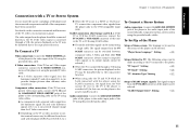
... Connect a TV 11 To Connect a Stereo System 11 To Set Up of the Player 11 Connection with an AV Amplifier 12 To Connect an AV Amplifier 13 To Setup of the Player 13 Chapter 2: Various Setups 14 Preparation of Remote Control Unit 14 Installing the batteries 14 Remote control range 14 Turning Power on DVD Discs 6 Region Codes of This Player (DVD VIDEO disc only 6 Region codes of Playable Discs 5 Unplayable Discs 5 Icons Inscribed on 14 Standby mode 14 Control Buttons Used in Setups 15 Basic Operations in Setup Screen...
... Connect a TV 11 To Connect a Stereo System 11 To Set Up of the Player 11 Connection with an AV Amplifier 12 To Connect an AV Amplifier 13 To Setup of the Player 13 Chapter 2: Various Setups 14 Preparation of Remote Control Unit 14 Installing the batteries 14 Remote control range 14 Turning Power on DVD Discs 6 Region Codes of This Player (DVD VIDEO disc only 6 Region codes of Playable Discs 5 Unplayable Discs 5 Icons Inscribed on 14 Standby mode 14 Control Buttons Used in Setups 15 Basic Operations in Setup Screen...
User Manual 1
Page 9
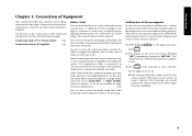
... blinking "INIT"(initializing), then shows "INIT OK!" (Ini- ON - Connection with a TV or Stereo System 0 Connection with an AV Amplifier @ Before Start Do not install the player in a place where the remote control sensor is left connected, malfunction or equipment damage may result. If a connection cable is connected or disconnected while the power plug is subjected to direct sunlight or the light of audio or noise may sometimes lead to speaker...
... blinking "INIT"(initializing), then shows "INIT OK!" (Ini- ON - Connection with a TV or Stereo System 0 Connection with an AV Amplifier @ Before Start Do not install the player in a place where the remote control sensor is left connected, malfunction or equipment damage may result. If a connection cable is connected or disconnected while the power plug is subjected to direct sunlight or the light of audio or noise may sometimes lead to speaker...

User Manual 1
Page 10
... OPTICAL DIGITAL OUTPUT (PCM/BIT STREAM) 1 2 1 L CENTER S VIDEO OUTPUT R Y Cb Cr 2 VIDEO COMPONENT VIDEO OUTPUT OUTPUT MIX LINE FRONT SURROUND SUB WOOFER OUTPUT 6CH. OUTPUT Select the video connection method according to the TV's input connector. and Europe): Connect the TV SCART connector to the TV in use. Connect the VCR SCART connector to the VCR's input connector. Connections Connection with a TV or Stereo System Chapter 1: Connection of Equipment Audio connection: To audio input jacks TV Audio cable (provided) Video connection: To video input jack Component...
... OPTICAL DIGITAL OUTPUT (PCM/BIT STREAM) 1 2 1 L CENTER S VIDEO OUTPUT R Y Cb Cr 2 VIDEO COMPONENT VIDEO OUTPUT OUTPUT MIX LINE FRONT SURROUND SUB WOOFER OUTPUT 6CH. OUTPUT Select the video connection method according to the TV's input connector. and Europe): Connect the TV SCART connector to the TV in use. Connect the VCR SCART connector to the VCR's input connector. Connections Connection with a TV or Stereo System Chapter 1: Connection of Equipment Audio connection: To audio input jacks TV Audio cable (provided) Video connection: To video input jack Component...
User Manual 1
Page 11
... the power cord plugs of the player and the connected components until all of the TV using the provided audio cables. To Connect a Stereo System Audio connection: Connect the MIX LINE OUTPUT jack of the player to the audio input jacks of the TV, refer to its output signals cannot be selected.) ¶ When the TV is connected through a VCR, the picture displayed on the connection terminals and functions of the connected audio component such as a stereo system using the provided video cable.
... the power cord plugs of the player and the connected components until all of the TV using the provided audio cables. To Connect a Stereo System Audio connection: Connect the MIX LINE OUTPUT jack of the player to the audio input jacks of the TV, refer to its output signals cannot be selected.) ¶ When the TV is connected through a VCR, the picture displayed on the connection terminals and functions of the connected audio component such as a stereo system using the provided video cable.

User Manual 1
Page 12
... jack Audio cables (provided) Digital audio connection: To digital audio input connector Video cable (provided) S Video connection: To S Video input connector S Video cable (provided) Optical fiber cable (provided) Used when the TV or VCR has the SCART connection capability. 0 TV SCART VCR SCART COAXIAL OPTICAL DIGITAL OUTPUT (PCM/BIT STREAM) Used when the AV amplifier and TV have the component video connection capability. 0 Used when the AV amp has 6-channel inputs. 1 2 1 L CENTER S VIDEO OUTPUT R Y Cb Cr 2 VIDEO COMPONENT VIDEO OUTPUT OUTPUT MIX LINE FRONT SURROUND SUB...
... jack Audio cables (provided) Digital audio connection: To digital audio input connector Video cable (provided) S Video connection: To S Video input connector S Video cable (provided) Optical fiber cable (provided) Used when the TV or VCR has the SCART connection capability. 0 TV SCART VCR SCART COAXIAL OPTICAL DIGITAL OUTPUT (PCM/BIT STREAM) Used when the AV amplifier and TV have the component video connection capability. 0 Used when the AV amp has 6-channel inputs. 1 2 1 L CENTER S VIDEO OUTPUT R Y Cb Cr 2 VIDEO COMPONENT VIDEO OUTPUT OUTPUT MIX LINE FRONT SURROUND SUB...
User Manual 1
Page 13
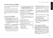
.... "Player Menu Language" Setting › Setups Related to TV: The following setups can be sure to them. ¶ When an amplifier which is not compatible with an AV Amplifier Do not insert the power cord plugs of the player and the connected components until all of the components have been connected. OUTPUT jacks output the same number of channels as the original number of channels regardless of the player to it using the provided video cable. S Video connection: When...
.... "Player Menu Language" Setting › Setups Related to TV: The following setups can be sure to them. ¶ When an amplifier which is not compatible with an AV Amplifier Do not insert the power cord plugs of the player and the connected components until all of the components have been connected. OUTPUT jacks output the same number of channels as the original number of channels regardless of the player to it using the provided video cable. S Video connection: When...

User Manual 1
Page 14
... referred to as the standby mode of the disc starts automatically. The player's tray starts rotation to the separate "User's Guide". plifier for the DVD player input. When no disc is inserted, the display shows "NO DISC" and the player enters stop the player. The setup operations are going to leave the listening room] When the power is on or standby, it , press the 3 button.) 3. Settings Preparation of Remote Control Unit Installing the batteries: Open the cover and insert...
... referred to as the standby mode of the disc starts automatically. The player's tray starts rotation to the separate "User's Guide". plifier for the DVD player input. When no disc is inserted, the display shows "NO DISC" and the player enters stop the player. The setup operations are going to leave the listening room] When the power is on or standby, it , press the 3 button.) 3. Settings Preparation of Remote Control Unit Installing the batteries: Open the cover and insert...

User Manual 1
Page 16
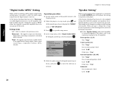
... according to set the audio output method when system components are connected using the 6CH. "IPB Display" Setting ¢ ¶ Switches the IPB display on /off . When the system is to be set the speakers, audio output during DVD or VCD search, dynamic range control function and audio filters. "On Screen Message" Setting £ ¶ Switches the on-screen message on /off . Settings Chapter 2: Various Setups When "MAIN" is 4:3. SOUND Digital Audio PCM Down Conversion 7 On MENU Dolby Digital DTS MPEG...
... according to set the audio output method when system components are connected using the 6CH. "IPB Display" Setting ¢ ¶ Switches the IPB display on /off . When the system is to be set the speakers, audio output during DVD or VCD search, dynamic range control function and audio filters. "On Screen Message" Setting £ ¶ Switches the on-screen message on /off . Settings Chapter 2: Various Setups When "MAIN" is 4:3. SOUND Digital Audio PCM Down Conversion 7 On MENU Dolby Digital DTS MPEG...

User Manual 1
Page 17
...rate. "Disc Menu Language" Setting › ¶ Sets the language used to display the menu screens, language use in system connection. "Subtitle Language" Setting fl ¶ Sets the language of the disc audio. "FL Mode" Setting ‡ ¶ Sets the brightness of the player. "Digital Audio Dolby Digital" Setting § ¶ Sets the Dolby Digital output. "Speaker Setting" • ¶ This setting is to set the still mode, FL mode, video format conversion system or TV SCART connector output signals. "Dynamic Range Control" Setting ¤ ¶ Switches the...
...rate. "Disc Menu Language" Setting › ¶ Sets the language used to display the menu screens, language use in system connection. "Subtitle Language" Setting fl ¶ Sets the language of the disc audio. "FL Mode" Setting ‡ ¶ Sets the brightness of the player. "Digital Audio Dolby Digital" Setting § ¶ Sets the Dolby Digital output. "Speaker Setting" • ¶ This setting is to set the still mode, FL mode, video format conversion system or TV SCART connector output signals. "Dynamic Range Control" Setting ¤ ¶ Switches the...
User Manual 1
Page 28
... speakers (L, R) Size: "Large" Center speaker (C) Size: "Large" Use of center speaker: Used Level: "0 dB" Delay time: "0 ms" Surround speakers (LS, RS) Size: "Large" Use of surround speakers: Used Level: "0 dB" Delay time: "0 ms" Subwoofer Use of the AV amplifier. When you want to change this setting is output as the connections are made. Settings Chapter 2: Various Setups "Digital Audio MPEG" Setting When a DVD recorded in stop mode, press 1 and SET UP tilt the joystick up or down to display the "SOUND" menu of "SET...
... speakers (L, R) Size: "Large" Center speaker (C) Size: "Large" Use of center speaker: Used Level: "0 dB" Delay time: "0 ms" Surround speakers (LS, RS) Size: "Large" Use of surround speakers: Used Level: "0 dB" Delay time: "0 ms" Subwoofer Use of the AV amplifier. When you want to change this setting is output as the connections are made. Settings Chapter 2: Various Setups "Digital Audio MPEG" Setting When a DVD recorded in stop mode, press 1 and SET UP tilt the joystick up or down to display the "SOUND" menu of "SET...

User Manual 1
Page 29
... front speakers: Select and adjust either "L" or "R". To set the center speaker: Select "C". Press ENTER to the screen in stop mode, press 1 and SET UP tilt the joystick up /down to be set the surround speakers: Select and adjust "LS" and "RS" separately. Settings Chapter 2: Various Setups Operation procedure 1. To output the test tone: Select "Test" To exit from the screen: Select "Exit" 6. Select "Large" when the connected speaker...
... front speakers: Select and adjust either "L" or "R". To set the center speaker: Select "C". Press ENTER to the screen in stop mode, press 1 and SET UP tilt the joystick up /down to be set the surround speakers: Select and adjust "LS" and "RS" separately. Settings Chapter 2: Various Setups Operation procedure 1. To output the test tone: Select "Test" To exit from the screen: Select "Exit" 6. Select "Large" when the connected speaker...

User Manual 1
Page 42
... OPEN. However, there is equipped with the limits for help. NOTE : This equipment has been tested and found to radio communications, if it is installed increases, etc. General Knowledge 42 Turn the player power on a circuit different from a place to operate this unit is not installed and used in the room where this equipment if an unauthorized change or modification is a discrete 5.1 channel digital audio...
... OPEN. However, there is equipped with the limits for help. NOTE : This equipment has been tested and found to radio communications, if it is installed increases, etc. General Knowledge 42 Turn the player power on a circuit different from a place to operate this unit is not installed and used in the room where this equipment if an unauthorized change or modification is a discrete 5.1 channel digital audio...


