
Instruction Manual
Page 1
STEREO/BRIDGEABLE POWER AMPLIFIER KAC-6202 INSTRUCTION MANUAL © B64-3043-00/00 (MV)
STEREO/BRIDGEABLE POWER AMPLIFIER KAC-6202 INSTRUCTION MANUAL © B64-3043-00/00 (MV)
Instruction Manual
Page 2
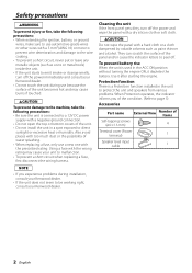
... a Protection function installed in the unit to protect the unit and speakers from various problems. When Protection operates, the indicator informs you experience problems during use because the surface of the unit becomes hot and may cause your unit to be working right, consult your Kenwood dealer. • If the unit does not seem to malfunction. • To prevent a short circuit when replacing a fuse, first disconnect the wiring harness. Use it depletes the battery...
... a Protection function installed in the unit to protect the unit and speakers from various problems. When Protection operates, the indicator informs you experience problems during use because the surface of the unit becomes hot and may cause your unit to be working right, consult your Kenwood dealer. • If the unit does not seem to malfunction. • To prevent a short circuit when replacing a fuse, first disconnect the wiring harness. Use it depletes the battery...
Instruction Manual
Page 3
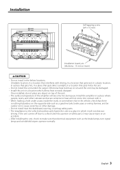
... unit comes off due to a shock and hits a person or safety part, it will not obstruct driving. Installation Ø4.6 330 mm 231 mm Self-tapping screw (ø4 × 16 mm) 227 mm 232 mm 242 mm Installation board, etc. (thickness : 15 mm or more) 2CAUTION • Do not install...turn signal lamps and windshield wipers operate normally. Once installed, do not place any object on the opposite side such as a gasoline tank, brake pipe, or wiring harness, and be damaged. • Install this unit in which allows heat to make sure that are sensitive to heat will become hot during use...
... unit comes off due to a shock and hits a person or safety part, it will not obstruct driving. Installation Ø4.6 330 mm 231 mm Self-tapping screw (ø4 × 16 mm) 227 mm 232 mm 242 mm Installation board, etc. (thickness : 15 mm or more) 2CAUTION • Do not install...turn signal lamps and windshield wipers operate normally. Once installed, do not place any object on the opposite side such as a gasoline tank, brake pipe, or wiring harness, and be damaged. • Install this unit in which allows heat to make sure that are sensitive to heat will become hot during use...
Instruction Manual
Page 4
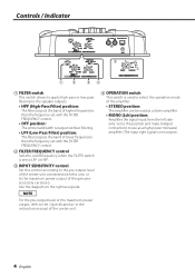
... lower frequencies than the frequency set with the FILTER FREQUENCY control. 2 FILTER FREQUENCY control Sets the cutoff frequency when the FILTER switch is set to LPF or HPF. 3 INPUT SENSITIVITY control Set this control according to the pre-output level of the center unit connected with this position and make bridged connections to use as a guide. NOTE For the pre-output level or the maximum power output, refer to the in the instruction manual of the center unit. 4 OPERATION switch This switch is used as a stereo amplifier. • MONO (Lch) position: Amplifies...
... lower frequencies than the frequency set with the FILTER FREQUENCY control. 2 FILTER FREQUENCY control Sets the cutoff frequency when the FILTER switch is set to LPF or HPF. 3 INPUT SENSITIVITY control Set this control according to the pre-output level of the center unit connected with this position and make bridged connections to use as a guide. NOTE For the pre-output level or the maximum power output, refer to the in the instruction manual of the center unit. 4 OPERATION switch This switch is used as a stereo amplifier. • MONO (Lch) position: Amplifies...
Instruction Manual
Page 5
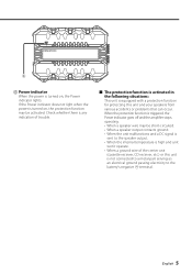
...; When the unit malfunctions and a DC signal is sent to the battery's negative - English 5 5 5 Power indicator When the power is not connected to a metal part serving as an electrical ground passing electricity to the speaker output. • When the internal temperature is high and unit won't operate. • When a ground wire of trouble. ■ The protection function is activated in the following situations: This unit is turned on , the Power indicator lights.
...; When the unit malfunctions and a DC signal is sent to the battery's negative - English 5 5 5 Power indicator When the power is not connected to a metal part serving as an electrical ground passing electricity to the speaker output. • When the internal temperature is high and unit won't operate. • When a ground wire of trouble. ■ The protection function is activated in the following situations: This unit is turned on , the Power indicator lights.
Instruction Manual
Page 6
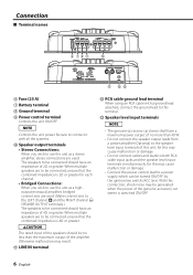
...cause malfunction or damage. • Connect the power control lead to be generated when the power of the amplifier. Connection ■ Terminal names 25 6 789 0 ! @# 6 Fuse (25 A) 7 Battery terminal 8 Ground terminal 9 Power control terminal Controls the unit ON/OFF. LINE IN terminal @ RCA cable ground lead terminal When using an RCA cable with all the systems. 0 Speaker output terminals • Stereo Connections: When you wish to use the unit as a highoutput monaural amplifier, bridged connections are to the speaker level input terminals of 2Ω or greater. Otherwise...
...cause malfunction or damage. • Connect the power control lead to be generated when the power of the amplifier. Connection ■ Terminal names 25 6 789 0 ! @# 6 Fuse (25 A) 7 Battery terminal 8 Ground terminal 9 Power control terminal Controls the unit ON/OFF. LINE IN terminal @ RCA cable ground lead terminal When using an RCA cable with all the systems. 0 Speaker output terminals • Stereo Connections: When you wish to use the unit as a highoutput monaural amplifier, bridged connections are to the speaker level input terminals of 2Ω or greater. Otherwise...
Instruction Manual
Page 7
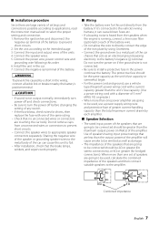
... the battery wire for this unit directly from unconnected wires or connectors to prevent short circuits. • Connect the speaker wires to prevent short circuits. 2. Sharing the negative wire of the speaker or grounding speaker wires to the metal body of the car can cause blown fuses etc. • If a buzzing noise is heard from the speakers when the engine is running, connect a line noise filter (optional) to each amplifier. ■ Speaker Selection • The rated input power...
... the battery wire for this unit directly from unconnected wires or connectors to prevent short circuits. • Connect the speaker wires to prevent short circuits. 2. Sharing the negative wire of the speaker or grounding speaker wires to the metal body of the car can cause blown fuses etc. • If a buzzing noise is heard from the speakers when the engine is running, connect a line noise filter (optional) to each amplifier. ■ Speaker Selection • The rated input power...
Instruction Manual
Page 8
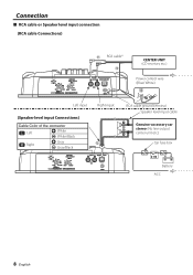
Connection ■ RCA cable or Speaker level input connection (RCA cable Connections) ! RCA cable* @ CENTER UNIT (CD receiver, etc.) Left input Right input (Speaker level input Connections) Cable Color of the connector Left White White/Black Right Gray # Gray/Black Power control wire (Blue/ White) @ GND RCA cable ground terminal Speaker level input cable Genuine-accessory car stereo (No line output center unit etc.) Car fuse box Battery ACC 8 English
Connection ■ RCA cable or Speaker level input connection (RCA cable Connections) ! RCA cable* @ CENTER UNIT (CD receiver, etc.) Left input Right input (Speaker level input Connections) Cable Color of the connector Left White White/Black Right Gray # Gray/Black Power control wire (Blue/ White) @ GND RCA cable ground terminal Speaker level input cable Genuine-accessory car stereo (No line output center unit etc.) Car fuse box Battery ACC 8 English
Instruction Manual
Page 9
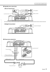
■ Speaker wire connection (Stereo Connections) 00 Lead terminal* (Bridged Connections) 0 25 * Commercially available parts Left speaker Right speaker Speaker (Bridged) 25 ■ Power wire connection 25 Terminal cover 789 Power control wire Battery wire* Ground wire* Protective Fuse* Battery Lead terminal* English 9
■ Speaker wire connection (Stereo Connections) 00 Lead terminal* (Bridged Connections) 0 25 * Commercially available parts Left speaker Right speaker Speaker (Bridged) 25 ■ Power wire connection 25 Terminal cover 789 Power control wire Battery wire* Ground wire* Protective Fuse* Battery Lead terminal* English 9
Instruction Manual
Page 11
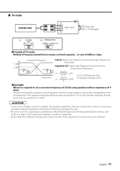
...-mode CENTER UNIT 1 L L RR 4 L C (High pass) C Subwoofer (L + R) (Bridged) ●Principle of Tri-mode Method of frequency band division using speakers with an impedance of 4 ohms. Prepare commercially-available coil and capacitor with an impedance lower than 4 ohms may damage the unit. • Be sure to connect capacitors to speakers to which high frequencies will result in case of the capacitors (C) and coils (L) are sufficient. The capacitor rating...
...-mode CENTER UNIT 1 L L RR 4 L C (High pass) C Subwoofer (L + R) (Bridged) ●Principle of Tri-mode Method of frequency band division using speakers with an impedance of 4 ohms. Prepare commercially-available coil and capacitor with an impedance lower than 4 ohms may damage the unit. • Be sure to connect capacitors to speakers to which high frequencies will result in case of the capacitors (C) and coils (L) are sufficient. The capacitor rating...
Instruction Manual
Page 12
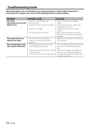
... problems. PROBLEM POSSIBLE CAUSE SOLUTION No sound. • Input (or output) cables are connected • Connect them properly checking the (The sound is not set improperly. • Set switches properly by a screw • Connect the speaker wire again so in your unit may be set to the correct to . 12 English position. cables. (Blown fuse.) • Protection circuit may be activated. • Check connections by referring to . • Volume is too high. • Replace the fuse and use lower volume...
... problems. PROBLEM POSSIBLE CAUSE SOLUTION No sound. • Input (or output) cables are connected • Connect them properly checking the (The sound is not set improperly. • Set switches properly by a screw • Connect the speaker wire again so in your unit may be set to the correct to . 12 English position. cables. (Blown fuse.) • Protection circuit may be activated. • Check connections by referring to . • Volume is too high. • Replace the fuse and use lower volume...
Instruction Manual
Page 13
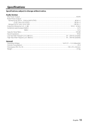
Specifications Specifications subject to Noise Ratio...100 dB Input Impedance...10 kΩ Low Pass Filter Frequency (12 dB/oct.) ...50 - 200 Hz (variable) High Pass Filter Frequency (12 dB/oct.)...50 - 200 Hz (variable) General Operating Voltage...14.4 V (11 - 16 V allowable) Current Consumption ...25 A Dimensions (W x H x D)...330 x 59 x 242 mm Weight...2.8 kg English 13 Audio Section Max Power Output ...400 W Rated Power Output Normal (4 Ω) (20 Hz - 20...
Specifications Specifications subject to Noise Ratio...100 dB Input Impedance...10 kΩ Low Pass Filter Frequency (12 dB/oct.) ...50 - 200 Hz (variable) High Pass Filter Frequency (12 dB/oct.)...50 - 200 Hz (variable) General Operating Voltage...14.4 V (11 - 16 V allowable) Current Consumption ...25 A Dimensions (W x H x D)...330 x 59 x 242 mm Weight...2.8 kg English 13 Audio Section Max Power Output ...400 W Rated Power Output Normal (4 Ω) (20 Hz - 20...


