
Instruction Manual
Page 1
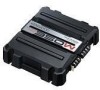
... power amplifier. KAC-5203 STEREO/BRIDGEABLE POWER AMPLIFIER 7 page 2-11 INSTRUCTION MANUAL AMPLIFICATEUR DE PUISSANCE STEREO/COMPATIBLE 7 page 12-21 MODE D'EMPLOI ESTÉREO/AMPLIFICADOR DE POTENCIA CONECTABLE 7 página 22-31 MANUAL DE INSTRUCCIONES Take the time to the model and serial numbers whenever you obtain the best performance from your Kenwood product at www.Kenwoodusa.com © B64-3531-00/00 (KV/EV) Familiarity with installation...
... power amplifier. KAC-5203 STEREO/BRIDGEABLE POWER AMPLIFIER 7 page 2-11 INSTRUCTION MANUAL AMPLIFICATEUR DE PUISSANCE STEREO/COMPATIBLE 7 page 12-21 MODE D'EMPLOI ESTÉREO/AMPLIFICADOR DE POTENCIA CONECTABLE 7 página 22-31 MANUAL DE INSTRUCCIONES Take the time to the model and serial numbers whenever you obtain the best performance from your Kenwood product at www.Kenwoodusa.com © B64-3531-00/00 (KV/EV) Familiarity with installation...

Instruction Manual
Page 2
..., battery, or ground wires, make sure to correct the interference by the professional importer of a vehicle into an outlet on a circuit different from that interference will help . Also avoid places with the wrong rating may cause your local authority for details in a spot exposed to malfunction. • To prevent a short circuit when replacing a fuse, first disconnect the wiring harness. Contact your unit to direct...
..., battery, or ground wires, make sure to correct the interference by the professional importer of a vehicle into an outlet on a circuit different from that interference will help . Also avoid places with the wrong rating may cause your local authority for details in a spot exposed to malfunction. • To prevent a short circuit when replacing a fuse, first disconnect the wiring harness. Contact your unit to direct...

Instruction Manual
Page 3
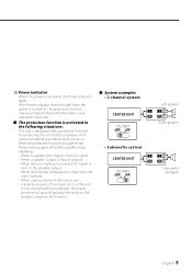
... unit and speakers from the battery. Protection function There is running, connect a line noise filter (optional) to be 2Ω or greater (for stereo connections), or 4Ω or greater (for this unit directly from various problems. When Protection operates, the indicator informs you of the condition. (Refer to page 5) Accessories Part name Self-tapping screws (ø4 × 16 mm) Terminal cover (Power terminal) Speaker level input cable External Number of the speakers that are less than the output power...
... unit and speakers from the battery. Protection function There is running, connect a line noise filter (optional) to be 2Ω or greater (for stereo connections), or 4Ω or greater (for this unit directly from various problems. When Protection operates, the indicator informs you of the condition. (Refer to page 5) Accessories Part name Self-tapping screws (ø4 × 16 mm) Terminal cover (Power terminal) Speaker level input cable External Number of the speakers that are less than the output power...

Instruction Manual
Page 4
...; Bridged Connections: When you wish to the speaker level input terminals of the genuineaccessory car stereo. When multiple speakers are used . Otherwise malfunction may cause malfunction or damage. • Connect the power control lead to be turned ON/OFF by the ignition key switch (ACC line). Use the diagram on the right as a stereo amplifier, stereo connections are to a power supply which can be connected, ensure that the combined impedance is switched ON/OFF. 5 Fuse (25 A) 6 Battery terminal 7 Ground terminal 8 Power control terminal Controls...
...; Bridged Connections: When you wish to the speaker level input terminals of the genuineaccessory car stereo. When multiple speakers are used . Otherwise malfunction may cause malfunction or damage. • Connect the power control lead to be turned ON/OFF by the ignition key switch (ACC line). Use the diagram on the right as a stereo amplifier, stereo connections are to a power supply which can be connected, ensure that the combined impedance is switched ON/OFF. 5 Fuse (25 A) 6 Battery terminal 7 Ground terminal 8 Power control terminal Controls...
Instruction Manual
Page 5
... a speaker wire may be short-circuited. • When a speaker output contacts ground. • When the unit malfunctions and a DC signal is sent to the battery's negative - If the Power indicator does not light when the power is not connected to a metal part serving as an electrical ground passing electricity to the speaker output. • When the internal temperature is high and unit won't operate. • When a ground wire of trouble. ■ The protection function...
... a speaker wire may be short-circuited. • When a speaker output contacts ground. • When the unit malfunctions and a DC signal is sent to the battery's negative - If the Power indicator does not light when the power is not connected to a metal part serving as an electrical ground passing electricity to the speaker output. • When the internal temperature is high and unit won't operate. • When a ground wire of trouble. ■ The protection function...
Instruction Manual
Page 6
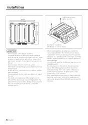
... as the brake lamps, turn signal lamps and windshield wipers operate normally. 6 English Otherwise heat build-up occurs and the unit may cause injury or an accident. • After installing the unit, check to make sure that electrical equipment such as a gasoline tank, brake pipe, or wiring harness, and be damaged. • Install this unit in a location which it...
... as the brake lamps, turn signal lamps and windshield wipers operate normally. 6 English Otherwise heat build-up occurs and the unit may cause injury or an accident. • After installing the unit, check to make sure that electrical equipment such as a gasoline tank, brake pipe, or wiring harness, and be damaged. • Install this unit in a location which it...

Instruction Manual
Page 7
... a short in the car. 7. Install the unit in the wiring, connect a fusible link or breaker nearby the battery's positive terminal. 2CAUTION • If sound is not output normally, immediately turn the power off before changing the setting of any switch. • If the fuse blows, check wires for shorts, then replace the fuse with one of the battery to appropriate speaker connectors separately. Connect the power wire, power control wire and grounding wire following this unit to the intended usage...
... a short in the car. 7. Install the unit in the wiring, connect a fusible link or breaker nearby the battery's positive terminal. 2CAUTION • If sound is not output normally, immediately turn the power off before changing the setting of any switch. • If the fuse blows, check wires for shorts, then replace the fuse with one of the battery to appropriate speaker connectors separately. Connect the power wire, power control wire and grounding wire following this unit to the intended usage...
Instruction Manual
Page 8
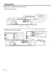
Connection ■ RCA cable or Speaker level input connection (RCA cable Connections) RCA cable* CENTER UNIT (CD receiver, etc.) Left input Right input (Speaker level input Connections) Cable Color of the connector Left White White/Black Right Gray Gray/Black Power control wire (Blue/ White) Speaker level input cable Genuine-accessory car stereo (No line output center unit etc.) Car fuse box Battery ACC 8 English
Connection ■ RCA cable or Speaker level input connection (RCA cable Connections) RCA cable* CENTER UNIT (CD receiver, etc.) Left input Right input (Speaker level input Connections) Cable Color of the connector Left White White/Black Right Gray Gray/Black Power control wire (Blue/ White) Speaker level input cable Genuine-accessory car stereo (No line output center unit etc.) Car fuse box Battery ACC 8 English
Instruction Manual
Page 9
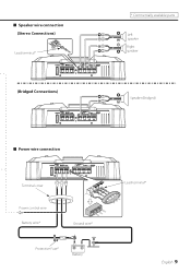
■ Speaker wire connection (Stereo Connections) Lead terminal* (Bridged Connections) 25 * Commercially available parts Left speaker Right speaker Speaker (Bridged) 25 ■ Power wire connection 25 Terminal cover Power control wire Battery wire* Ground wire* Protective Fuse* Battery Lead terminal* English 9
■ Speaker wire connection (Stereo Connections) Lead terminal* (Bridged Connections) 25 * Commercially available parts Left speaker Right speaker Speaker (Bridged) 25 ■ Power wire connection 25 Terminal cover Power control wire Battery wire* Ground wire* Protective Fuse* Battery Lead terminal* English 9

Instruction Manual
Page 10
... to . The output level is not set improperly. • Set switches properly by a screw • Connect the speaker wire again so in your unit may just be activated. • Check connections by referring to . • Volume is too high. • Replace the fuse and use lower volume. • The speaker cord is shorted. • After check the speaker cord and fixing the cause of slight misoperation or miswiring. Troubleshooting Guide What might...
... to . The output level is not set improperly. • Set switches properly by a screw • Connect the speaker wire again so in your unit may just be activated. • Check connections by referring to . • Volume is too high. • Replace the fuse and use lower volume. • The speaker cord is shorted. • After check the speaker cord and fixing the cause of slight misoperation or miswiring. Troubleshooting Guide What might...
Instruction Manual
Page 11
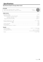
... Watts per channel @ 4 ohms, 1 % THD+N 55 W × 2 Signal to Noise Ratio (Reference: 1Watt into 4 ohms 80 dBA Audio Section Max Power Output ...350 W Rated Power Output Normal (4 Ω) (20 Hz - 20 kHz, 0.08 % THD)...55 W × 2 Normal (4 Ω) (DIN : 45324 , +B = 14.4V) ...55 W × 2 Normal (2 Ω) (1 kHz, 0.8 % THD)...75 W × 2 Bridged (4 Ω) (1 kHz, 0.8 % THD)...150 W × 1 Frequency Response (+0, -3 dB) ...5 Hz - 50 kHz Sensitivity (rated output) (MAX...
... Watts per channel @ 4 ohms, 1 % THD+N 55 W × 2 Signal to Noise Ratio (Reference: 1Watt into 4 ohms 80 dBA Audio Section Max Power Output ...350 W Rated Power Output Normal (4 Ω) (20 Hz - 20 kHz, 0.08 % THD)...55 W × 2 Normal (4 Ω) (DIN : 45324 , +B = 14.4V) ...55 W × 2 Normal (2 Ω) (1 kHz, 0.8 % THD)...75 W × 2 Bridged (4 Ω) (1 kHz, 0.8 % THD)...150 W × 1 Frequency Response (+0, -3 dB) ...5 Hz - 50 kHz Sensitivity (rated output) (MAX...


