Installation Instructions
Page 1
... this or any phone in the Use & Care Guide., read it carefully. • Be sure your gas supplier from the oven compartments before installing range. do not use gasoline or other appliance. = WHAT TO DO iF YOU SMELL GAS: • Do not try to your gas supplier, call your range is installed... other flammable vapors and liquids in these instructions with your Use & Care Guide for future reference. = As when using any electrical switch; Make sure the wall coverings around the range can withstand the heat generated by the range. Paginas 13-24
... this or any phone in the Use & Care Guide., read it carefully. • Be sure your gas supplier from the oven compartments before installing range. do not use gasoline or other appliance. = WHAT TO DO iF YOU SMELL GAS: • Do not try to your gas supplier, call your range is installed... other flammable vapors and liquids in these instructions with your Use & Care Guide for future reference. = As when using any electrical switch; Make sure the wall coverings around the range can withstand the heat generated by the range. Paginas 13-24
Installation Instructions
Page 2
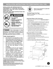
...safety precautions you place an insulating pad or sheet of 1/4-inch thick plywood between the range and carpeting. = Make sure the wall coverings around the base or beneath the lower front panel of Massachusetts by CSA International. Children could result. When using a ...the room. Install only per installation instructions provided in an area covered with any other utensils before self-cleaning the oven. As with linoleum or any appliance using a programmable timing operation. Special instructions for proper burner combustion. A "T" handle type manual gas valve must ...
...safety precautions you place an insulating pad or sheet of 1/4-inch thick plywood between the range and carpeting. = Make sure the wall coverings around the base or beneath the lower front panel of Massachusetts by CSA International. Children could result. When using a ...the room. Install only per installation instructions provided in an area covered with any other utensils before self-cleaning the oven. As with linoleum or any appliance using a programmable timing operation. Special instructions for proper burner combustion. A "T" handle type manual gas valve must ...
Installation Instructions
Page 3
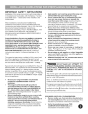
... pipe elbow (Fig. 17). Electric drill & 1/8" dia. For burner flame adjustment: Phillips head and small blade-type screwdrivers (Figs. 9& 10). A new flexible metal appliance conduit (1/2" N PT x 3/4" or 1/2" I .D.) supplied with range - Always use the (2) new flare adapters (1/2" NPT x 3/4" or 1/2" I .D.) must be design... (48" MAXIMUM LENGTH)for each new installation and additional reinstallations. Fig. 20). = 4 or 3 wire, 40/50 ampere rated wall receptacle and mounting plate (Fig. 21). = Copper electrical wiring and metal conduit (for hard wiring installation only). bit (5/32" Masonry...
... pipe elbow (Fig. 17). Electric drill & 1/8" dia. For burner flame adjustment: Phillips head and small blade-type screwdrivers (Figs. 9& 10). A new flexible metal appliance conduit (1/2" N PT x 3/4" or 1/2" I .D.) supplied with range - Always use the (2) new flare adapters (1/2" NPT x 3/4" or 1/2" I .D.) must be design... (48" MAXIMUM LENGTH)for each new installation and additional reinstallations. Fig. 20). = 4 or 3 wire, 40/50 ampere rated wall receptacle and mounting plate (Fig. 21). = Copper electrical wiring and metal conduit (for hard wiring installation only). bit (5/32" Masonry...
Installation Instructions
Page 6
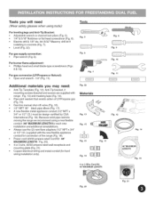
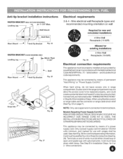
i_ tJ _F Wall M°unt -- More Than 1 =1/4" i Fig. 25 Fig. 26 Fig. 27 Electrical requirements 3 & 4 - This appliance may be connected by means of permanent "Hard Wiring" or "Power Supply Cord Kit." Cord must have strain relief ... conductors (See Fig. 28). Wire electrical wall Receptacle types and recommended mounting orientation on wall Required for new and remodeled installations 4 Wire Wall Receptacle (14150R) Allowed for exisiting installations 3 Wire Wall Receptacle (10=50R) Fig. 28 Electrical connection requirements This appliance must be either closed loop or open-end ...
i_ tJ _F Wall M°unt -- More Than 1 =1/4" i Fig. 25 Fig. 26 Fig. 27 Electrical requirements 3 & 4 - This appliance may be connected by means of permanent "Hard Wiring" or "Power Supply Cord Kit." Cord must have strain relief ... conductors (See Fig. 28). Wire electrical wall Receptacle types and recommended mounting orientation on wall Required for new and remodeled installations 4 Wire Wall Receptacle (14150R) Allowed for exisiting installations 3 Wire Wall Receptacle (10=50R) Fig. 28 Electrical connection requirements This appliance must be either closed loop or open-end ...
Installation Instructions
Page 7
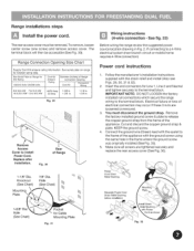
...See Fig. 30). Connect the ground wire (Green) lead with the eyelet to the terminal block. Replace after installation. Fig. 30 Rear of the appliance with the strain relief and install (Also see Figs. 29, 30, 31 & 32). 2. IMPORTANT NOTE: DO NOT LOOSEN the factory installed nut connections... which secure the range wiring to install Power Cord. If connecting to release the copper ground strap from the frame of the appliance. KEEP the ground screw. 4. The terminal block will then be removed. See serial plate on Range for kilowatt rating data. See Serial...
...See Fig. 30). Connect the ground wire (Green) lead with the eyelet to the terminal block. Replace after installation. Fig. 30 Rear of the appliance with the strain relief and install (Also see Figs. 29, 30, 31 & 32). 2. IMPORTANT NOTE: DO NOT LOOSEN the factory installed nut connections... which secure the range wiring to install Power Cord. If connecting to release the copper ground strap from the frame of the appliance. KEEP the ground screw. 4. The terminal block will then be removed. See serial plate on Range for kilowatt rating data. See Serial...
Installation Instructions
Page 9
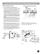
... 4. (4-Wire Permanent Connection ONLY} Connectthe ground wire lead (Green) to release the factory installed copper ground strap from frame of the appliance. Remove the factory installed ground screw & plate to the frame of the permanent wiring for Line 1, Line 2, Neutral (also strip ... Non-terminated field wire compression connections must be set at approximately 22in./Ibs. Electrical failure or loss of Gas Supply ) Flexible Appliance Conduit Pressure Regulator Flare Adaptor ..........A...daptor Shutoff Black Pipe Fig. 37 Off Always use 10 ga. wire or larger. DO NOT...
... 4. (4-Wire Permanent Connection ONLY} Connectthe ground wire lead (Green) to release the factory installed copper ground strap from frame of the appliance. Remove the factory installed ground screw & plate to the frame of the permanent wiring for Line 1, Line 2, Neutral (also strip ... Non-terminated field wire compression connections must be set at approximately 22in./Ibs. Electrical failure or loss of Gas Supply ) Flexible Appliance Conduit Pressure Regulator Flare Adaptor ..........A...daptor Shutoff Black Pipe Fig. 37 Off Always use 10 ga. wire or larger. DO NOT...
Installation Instructions
Page 10
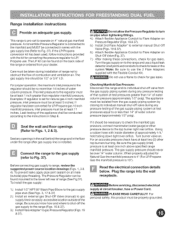
... Adapter on . Leak testing of combustion and ventilation air. Do not allow the Pressure Regulator to turn on pipe when tightening fittings. 4.) Attach flexible Appliance Conduit to Flare Adapter on Pressure Regulator (Figs. 18 & 37). 5.) Install 2nd Flare Adapter* to external manual Shut-Off Valve (Figs. 19 ...be conducted according to the top burner right rear orifice. Seal the wall and floor openings (Refer to Fig. 37). If it should never be at test pressures greater than regulator manifold pressure. The appliance must be over orifice. The LP Kit can be isolated from ...
... Adapter on . Leak testing of combustion and ventilation air. Do not allow the Pressure Regulator to turn on pipe when tightening fittings. 4.) Attach flexible Appliance Conduit to Flare Adapter on Pressure Regulator (Figs. 18 & 37). 5.) Install 2nd Flare Adapter* to external manual Shut-Off Valve (Figs. 19 ...be conducted according to the top burner right rear orifice. Seal the wall and floor openings (Refer to Fig. 37). If it should never be at test pressures greater than regulator manifold pressure. The appliance must be over orifice. The LP Kit can be isolated from ...
Installation Instructions
Page 11
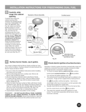
...been purged from supply lines by placing a level horizontally on Cooktop Burner Skirts. 6. Each burner should sit flat on an oven rack (See Fig. 27). The range has separate electrodes (igniters) for proper lighting, push in and turn the control knob out of electric igniters should...packing material located under center of surface burners. Note: The Burner Heads should light within four (4) seconds in use. Preshape the flexible appliance conduit and power cord if necessary to electric power. 1. Remove all burner valves have been carefully checked for leaks and range has been...
...been purged from supply lines by placing a level horizontally on Cooktop Burner Skirts. 6. Each burner should sit flat on an oven rack (See Fig. 27). The range has separate electrodes (igniters) for proper lighting, push in and turn the control knob out of electric igniters should...packing material located under center of surface burners. Note: The Burner Heads should light within four (4) seconds in use. Preshape the flexible appliance conduit and power cord if necessary to electric power. 1. Remove all burner valves have been carefully checked for leaks and range has been...
Installation Instructions
Page 12
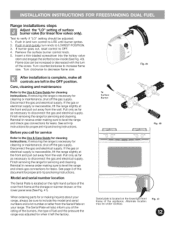
...screw. After installation is inaccessible, lift the range slightly at the front and pull out away from the wall. If removing the range is located on the right-hand surface of the appliance. Finish removing the range for cleaning instructions. Before you of the rating of the burners, the type ... increase flame size. Remove the surface burner control knob. 5. If the gas or electrical supply is located on the Iowerrig front frame of the oven front frame at the storage or warmer drawer; Pull only as far as necessary to the Use & Care Guide for cleaning instructions. Model and...
...screw. After installation is inaccessible, lift the range slightly at the front and pull out away from the wall. If removing the range is located on the right-hand surface of the appliance. Finish removing the range for cleaning instructions. Before you of the rating of the burners, the type ... increase flame size. Remove the surface burner control knob. 5. If the gas or electrical supply is located on the Iowerrig front frame of the oven front frame at the storage or warmer drawer; Pull only as far as necessary to the Use & Care Guide for cleaning instructions. Model and...