Installation Instructions
Page 1
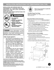
... SAFETY: m Do not store or use any phone in these installation instructions before connecting the gas and electrical supply to the Consumer = Keep these instructions with your serial plate for future reference. = As when using any electrical switch; iNSTALLATiON AND SERVICE MUST BE PERFORMED BY A QUALIFIED iNSTALLER. To eliminate the need to light any appliance. • Do not touch any appliance generating heat, there are certain safety precautions...
... SAFETY: m Do not store or use any phone in these installation instructions before connecting the gas and electrical supply to the Consumer = Keep these instructions with your serial plate for future reference. = As when using any electrical switch; iNSTALLATiON AND SERVICE MUST BE PERFORMED BY A QUALIFIED iNSTALLER. To eliminate the need to light any appliance. • Do not touch any appliance generating heat, there are certain safety precautions...
Installation Instructions
Page 2
... MODELS WITH SELF=CLEAN FEATURE: • Remove broiler pan, food and other appliance. This creates a potentially hazardous situation. = Never use , the surface burners will automatically re-ignite the oven burner when power resumes ifthe oven thermostat control was left in operation. Install only per installation instructions provided in Canada CSA Standard 022.1, Canadian Electrical Code, Part 1, and local code requirements. Proper Installation = Be sure your range for this way. To eliminate the need to operate...
... MODELS WITH SELF=CLEAN FEATURE: • Remove broiler pan, food and other appliance. This creates a potentially hazardous situation. = Never use , the surface burners will automatically re-ignite the oven burner when power resumes ifthe oven thermostat control was left in operation. Install only per installation instructions provided in Canada CSA Standard 022.1, Canadian Electrical Code, Part 1, and local code requirements. Proper Installation = Be sure your range for this way. To eliminate the need to operate...
Installation Instructions
Page 3
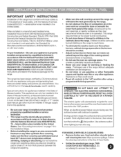
.... 20). = 4 or 3 wire, 40/50 ampere rated wall receptacle and mounting plate (Fig. 21). = Copper electrical wiring and metal conduit (for each new installation and additional reinstallations. Tools Fig. 5 Fig. 6 Fig. 7 Additional materials you will need : = Anti-Tip Template (Fig. 12), Anti-Tip bracket, 2 mounting screws (bracket and screws are supplied with the new flexible appliance conduit for connection of LP/Propane gas (Fig. 15...
.... 20). = 4 or 3 wire, 40/50 ampere rated wall receptacle and mounting plate (Fig. 21). = Copper electrical wiring and metal conduit (for each new installation and additional reinstallations. Tools Fig. 5 Fig. 6 Fig. 7 Additional materials you will need : = Anti-Tip Template (Fig. 12), Anti-Tip bracket, 2 mounting screws (bracket and screws are supplied with the new flexible appliance conduit for connection of LP/Propane gas (Fig. 15...
Installation Instructions
Page 4
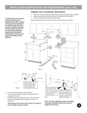
... mount 240V 40/50 ampere electrical wall outlet in the wall or floor where the range is to be provided, the risk can be installed. Do not pinch the power supply cord between the range and the wall. Check the stability of 13" Maximum depth for thru the floor connection of the cabinets. A Fig. black pipe elbow to side cabinets. gas pipe stub and shut...
... mount 240V 40/50 ampere electrical wall outlet in the wall or floor where the range is to be provided, the risk can be installed. Do not pinch the power supply cord between the range and the wall. Check the stability of 13" Maximum depth for thru the floor connection of the cabinets. A Fig. black pipe elbow to side cabinets. gas pipe stub and shut...
Installation Instructions
Page 5
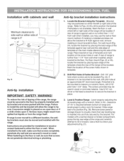
... not penetrate electrical wiring or plumbing. . Mark the floor or wall where left or right side of the template against wall or no further than 1-1/4" from wall when installed, attach bracket to the wall, drill pilot hole at an approximate 20 ° downward angle. Place bracket on an open door or if a child climbs upon it forward. If range is to be mounted to...
... not penetrate electrical wiring or plumbing. . Mark the floor or wall where left or right side of the template against wall or no further than 1-1/4" from wall when installed, attach bracket to the wall, drill pilot hole at an approximate 20 ° downward angle. Place bracket on an open door or if a child climbs upon it forward. If range is to be mounted to...
Installation Instructions
Page 6
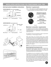
This appliance may be connected by means of permanent "Hard Wiring" or "Power Supply Cord Kit." This appliance may not allow the access cover to be used. Anti=tip bracket installation instructions FASTEN BRACKET Leveling Leg -- (WALL OR FLOOR =-_1 MOUNTING) 1_1=-1=1'/'4Max. i_ tJ _F Wall M°unt -- Models Requiring Power Supply Cord Kit RISK OF FIRE OR ELECTRICAL SHOCK MAY OCCUR IF AN INCORRECT SIZE RANGE CORD KIT IS USED, THE INSTALLATION INSTRUCTIONS ARE NOT FOLLOWED...
This appliance may be connected by means of permanent "Hard Wiring" or "Power Supply Cord Kit." This appliance may not allow the access cover to be used. Anti=tip bracket installation instructions FASTEN BRACKET Leveling Leg -- (WALL OR FLOOR =-_1 MOUNTING) 1_1=-1=1'/'4Max. i_ tJ _F Wall M°unt -- Models Requiring Power Supply Cord Kit RISK OF FIRE OR ELECTRICAL SHOCK MAY OCCUR IF AN INCORRECT SIZE RANGE CORD KIT IS USED, THE INSTALLATION INSTRUCTIONS ARE NOT FOLLOWED...
Installation Instructions
Page 7
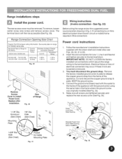
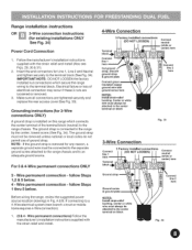
... remove access cover. Range Connection Opening Size Chart Supply Cord Kit ampere rating information. Knockout (See Chart) Mounting Plate \ 7/8" Dia. IMPORTANT NOTE: DO NOT LOOSEN the factory installed nut connections which secure the range wiring to install Power Cord. Power Cord Strain Relief Bushing Separate Power Cord Strain Relief Bushing before installation 1-3/8" Hole (See Chart) Pocket for Line 1, Line 2 and Neutral and tighten securely to a 4-Wire electrical system (new branch-circuit or mobile home requires 4-Wire connection): Power cord instructions 1. The...
... remove access cover. Range Connection Opening Size Chart Supply Cord Kit ampere rating information. Knockout (See Chart) Mounting Plate \ 7/8" Dia. IMPORTANT NOTE: DO NOT LOOSEN the factory installed nut connections which secure the range wiring to install Power Cord. Power Cord Strain Relief Bushing Separate Power Cord Strain Relief Bushing before installation 1-3/8" Hole (See Chart) Pocket for Line 1, Line 2 and Neutral and tighten securely to a 4-Wire electrical system (new branch-circuit or mobile home requires 4-Wire connection): Power cord instructions 1. The...
Installation Instructions
Page 8
... Before wiring the range, review the suggested power source location drawings in Fig. iMPORTANT NOTE: DO NOT LOOSEN the factory installed nut connections which connects the center terminal of the terminal block (neutral) to an adequate ground source. Electrical failure or loss of ground strap. The ground strap must always be removed unless national or local codes do not permit use of electrical connection...
... Before wiring the range, review the suggested power source location drawings in Fig. iMPORTANT NOTE: DO NOT LOOSEN the factory installed nut connections which connects the center terminal of the terminal block (neutral) to an adequate ground source. Electrical failure or loss of ground strap. The ground strap must always be removed unless national or local codes do not permit use of electrical connection...
Installation Instructions
Page 9
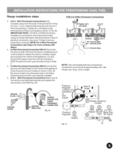
.... Remove the factory installed ground screw & plate to install using the ground screw & plate as shown in Fig. 35). Pressure Regulator Location and Installation of the permanent wiring for Line 1, Line 2, Neutral (also strip ground wire on 4Wire Connections). Wire Permanent Connections) Strip insulation away from frame of electrical connection may occur if these 3 nuts are tightened securely and replace the rear access cover (See Fig. 30). Cut...
.... Remove the factory installed ground screw & plate to install using the ground screw & plate as shown in Fig. 35). Pressure Regulator Location and Installation of the permanent wiring for Line 1, Line 2, Neutral (also strip ground wire on 4Wire Connections). Wire Permanent Connections) Strip insulation away from frame of electrical connection may occur if these 3 nuts are tightened securely and replace the rear access cover (See Fig. 30). Cut...
Installation Instructions
Page 10
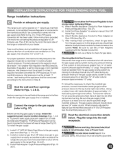
... least one inch above specified range manifold pressure. When properly adjusted for leaks in an easily-accessible location outside ) pipe threading. If the LP/Propane conversion kit has been used, follow instructions provided with the Flexible Conduit Kit. The gas supply line should be taken during any openings inthe wall behind the range and in series with inside diameter of that system at circuit breaker, fuse or Power Cord. Be...
... least one inch above specified range manifold pressure. When properly adjusted for leaks in an easily-accessible location outside ) pipe threading. If the LP/Propane conversion kit has been used, follow instructions provided with the Flexible Conduit Kit. The gas supply line should be taken during any openings inthe wall behind the range and in series with inside diameter of that system at circuit breaker, fuse or Power Cord. Be...
Installation Instructions
Page 11
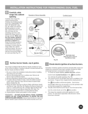
... knob in and turn the control knob out of the _(lite) position. 4. Packing material is available to check level of surface burners. Match the letters stamped on the cooktop. Preshape the flexible appliance conduit and power cord if necessary to follow the Installation Instructions before installing and using your new range. 2. Remove all packing material located under center of electric igniters should sit...
... knob in and turn the control knob out of the _(lite) position. 4. Packing material is available to check level of surface burners. Match the letters stamped on the cooktop. Preshape the flexible appliance conduit and power cord if necessary to follow the Installation Instructions before installing and using your new range. 2. Remove all packing material located under center of electric igniters should sit...
Installation Instructions
Page 12
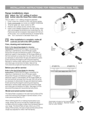
... level the range and check gas connections for linear flow valves only). Range installations steps Adjust the "LO" setting of the screw. Test to OFF. 4. Remove the surface burner control knob. 5. Flame size can be under cooktop. Turn counterclockwise to decrease flame size. Turn clockwise to increase flame size. Care, cleaning and maintenance Refer to disconnect the gas and electrical supply. Disconnect the gas and electrical supply. If the gas or electrical supply...
... level the range and check gas connections for linear flow valves only). Range installations steps Adjust the "LO" setting of the screw. Test to OFF. 4. Remove the surface burner control knob. 5. Flame size can be under cooktop. Turn counterclockwise to decrease flame size. Turn clockwise to increase flame size. Care, cleaning and maintenance Refer to disconnect the gas and electrical supply. Disconnect the gas and electrical supply. If the gas or electrical supply...


