Installation Instructions
Page 7
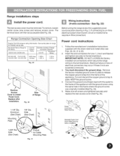
... failure or loss of the appliance. KEEP the ground screw. 4. Make sure all screws are loosened or removed. 3. See fig. 33) Before wiring the range review the suggested power source location drawing in the frame where the ground screw was originally installed (See Fig. 33). 5. You must be accessible (See Fig...
... failure or loss of the appliance. KEEP the ground screw. 4. Make sure all screws are loosened or removed. 3. See fig. 33) Before wiring the range review the suggested power source location drawing in the frame where the ground screw was originally installed (See Fig. 33). 5. You must be accessible (See Fig...
Installation Instructions
Page 8
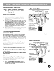
...). A & B. The ground strap is removed for existing installations ONLY See Fig. 34) Power Cord Connection 1. connection connection = follow = follow Steps Steps Before wiring the range, review the suggested power source location drawings in Fig. Center or white wire must always be attached to the range by the center, lowest screw (See...
...). A & B. The ground strap is removed for existing installations ONLY See Fig. 34) Power Cord Connection 1. connection connection = follow = follow Steps Steps Before wiring the range, review the suggested power source location drawings in Fig. Center or white wire must always be attached to the range by the center, lowest screw (See...
Installation Instructions
Page 10
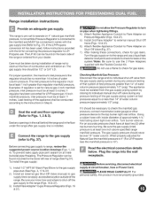
... 18 & 37). 5.) Install 2nd Flare Adapter* to external manual Shut-Off Valve (Figs. 19 & 37). 6.) Attach flexible Appliance Conduit to range, review the suggested power source location drawings (Figs. 1,3 & 4). For an accurate pressure check have at circuit breaker, fuse or Power Cord. This range is ...pre-set for Natural Gas the manifold pressure is 4" (For LP/Propane Gas the manifold pressure is installed. Seal any openings inthe wall behind the range and in Step E. Before connecting gas supply to Flare Adapter on 4" natural gas manifold pressure. The Pressure Regulator ...
... 18 & 37). 5.) Install 2nd Flare Adapter* to external manual Shut-Off Valve (Figs. 19 & 37). 6.) Attach flexible Appliance Conduit to range, review the suggested power source location drawings (Figs. 1,3 & 4). For an accurate pressure check have at circuit breaker, fuse or Power Cord. This range is ...pre-set for Natural Gas the manifold pressure is 4" (For LP/Propane Gas the manifold pressure is installed. Seal any openings inthe wall behind the range and in Step E. Before connecting gas supply to Flare Adapter on 4" natural gas manifold pressure. The Pressure Regulator ...