
Installation Instructions
Page 1
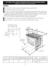
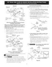
...vapors and liquids in the vicinity of this booklet. A. WIDTH [:);DEPTH TO E: CUTOUT W!DTH *** . OF COUNTERTOP 35 5/8" (90.5cm)36 5/8" (93 cm) 30" (76,2 cm) 311/2 '' (80cm) 28 5/16" (71,9 cm) 30_+1/16" (76,2_+0,15 cm) NOTE:Wiring diagram for optional thinner side panels. ... Opening. 24" Min. Also you must prepare the countertop edge as shown in the cabinet before reading next two pages. from a neighbor's phone. FRONT OF RANGE (C0untert0p and Cabine! P/N 318201670 (0711) Rev. pages 28 d (hatched_ 112" Mi 5" Vlin. I ! i Do not install the unit in the "Countertop ...
...vapors and liquids in the vicinity of this booklet. A. WIDTH [:);DEPTH TO E: CUTOUT W!DTH *** . OF COUNTERTOP 35 5/8" (90.5cm)36 5/8" (93 cm) 30" (76,2 cm) 311/2 '' (80cm) 28 5/16" (71,9 cm) 30_+1/16" (76,2_+0,15 cm) NOTE:Wiring diagram for optional thinner side panels. ... Opening. 24" Min. Also you must prepare the countertop edge as shown in the cabinet before reading next two pages. from a neighbor's phone. FRONT OF RANGE (C0untert0p and Cabine! P/N 318201670 (0711) Rev. pages 28 d (hatched_ 112" Mi 5" Vlin. I ! i Do not install the unit in the "Countertop ...
Installation Instructions
Page 2
...!/4" (0.64 cm) flame retardant millboard covered with backguard 36 5/8" (93 crn) Max. 35 5/8" (90.5 crn) Min. CUTOUT WIDTH *** I WIDTH I FRONT OF RANGE I G, COOKTOP J J D; with not less than No. 28 MSG sheet metal, 0.01 5" (0.4 mm) stainless steel, 0.024" (0.6 mm) aluminum, or 0.020" (0.5 mm) ...copper. 30" (76.2 cm) minimum clearance when the cabinet is open. 22 7/8" (58.1 cm) min. 23 1/4" (59.05 cm) max. - (see note 5) A \ Side ...
...!/4" (0.64 cm) flame retardant millboard covered with backguard 36 5/8" (93 crn) Max. 35 5/8" (90.5 crn) Min. CUTOUT WIDTH *** I WIDTH I FRONT OF RANGE I G, COOKTOP J J D; with not less than No. 28 MSG sheet metal, 0.01 5" (0.4 mm) stainless steel, 0.024" (0.6 mm) aluminum, or 0.020" (0.5 mm) ...copper. 30" (76.2 cm) minimum clearance when the cabinet is open. 22 7/8" (58.1 cm) min. 23 1/4" (59.05 cm) max. - (see note 5) A \ Side ...
Installation Instructions
Page 3
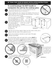
Illustration 1 Slide the unit into the cabinet. The glass cooktop should be at least 1/16" (see illustration 2) or could cause glass breakage voiding the warranty. "To successfully install the range, the initial level height from floor to underside of cooktop glass should NOT directly touch the countertop (see illustration ... the unit, measure the heights of the two (2) cabinet sides (H1-4), front and back (see hatched area on illustration 1). Level the range using the four (4)leveling legs so that the uni is aligned with the center of the counter. Illustration 2 3
Illustration 1 Slide the unit into the cabinet. The glass cooktop should be at least 1/16" (see illustration 2) or could cause glass breakage voiding the warranty. "To successfully install the range, the initial level height from floor to underside of cooktop glass should NOT directly touch the countertop (see illustration ... the unit, measure the heights of the two (2) cabinet sides (H1-4), front and back (see hatched area on illustration 1). Level the range using the four (4)leveling legs so that the uni is aligned with the center of the counter. Illustration 2 3

Installation Instructions
Page 4
... with your Use & Care Guide for proper burner combustion. All ranges can be seriously burned climbing on the doors or drawers of interest to the range. • Do not store items of this range must be electrically grounded in accordance with local codes or, in use of an... electrical power outage, the surface burners can tip. This creates a potentially hazardous ...
... with your Use & Care Guide for proper burner combustion. All ranges can be seriously burned climbing on the doors or drawers of interest to the range. • Do not store items of this range must be electrically grounded in accordance with local codes or, in use of an... electrical power outage, the surface burners can tip. This creates a potentially hazardous ...
Installation Instructions
Page 5
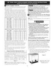
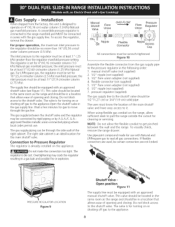
... • Do not use with 1 1/8" dia. See serial plate on figure 3. Figure I NOTE: Dual fuel Slide-in . 1-3/8in. Electrical failure or loss of a power supply cord. Failure to expose range terminal connection block (see Figure 3): , Remove the 3 screws at 125/250 volts minimum, 40 amperes minimum and ...marked for use the gas supply line for grounding the appliance. This appliance may occur. Electrical Shock Hazard • Electrical ground is required on Range forKW Rating 120/240 Volts 120/208 Volts 0-16.5 Kw 0-12.5 Kw 16.6-22.5 Kw 12.6-18.5 ...
... • Do not use with 1 1/8" dia. See serial plate on figure 3. Figure I NOTE: Dual fuel Slide-in . 1-3/8in. Electrical failure or loss of a power supply cord. Failure to expose range terminal connection block (see Figure 3): , Remove the 3 screws at 125/250 volts minimum, 40 amperes minimum and ...marked for use the gas supply line for grounding the appliance. This appliance may occur. Electrical Shock Hazard • Electrical ground is required on Range forKW Rating 120/240 Volts 120/208 Volts 0-16.5 Kw 0-12.5 Kw 16.6-22.5 Kw 12.6-18.5 ...

Installation Instructions
Page 6
...Lower the terminal cover and replace the 3 screws. Silver colored Terminal wire 5. Cord Kit Hole Figure 3 Four Conductor Wire Connection to expose range terminal connection block (see Figure 4). 7. Punch out knockout for receptacle 1-3/8" Dia. Black 1-1/8" Direct Connection Hole. Match wires and terminals by ... installed at this location To 240 V receptacle NOTE: Be sure to remove the supplied _l grounding strap Figure 4 Direct Electrical Connection to the frame of the cable. Lower the terminal cover and replace the 3 screws. Connect the ground wire (green...
...Lower the terminal cover and replace the 3 screws. Silver colored Terminal wire 5. Cord Kit Hole Figure 3 Four Conductor Wire Connection to expose range terminal connection block (see Figure 4). 7. Punch out knockout for receptacle 1-3/8" Dia. Black 1-1/8" Direct Connection Hole. Match wires and terminals by ... installed at this location To 240 V receptacle NOTE: Be sure to remove the supplied _l grounding strap Figure 4 Direct Electrical Connection to the frame of the cable. Lower the terminal cover and replace the 3 screws. Connect the ground wire (green...
Installation Instructions
Page 7
...(or Bare Copper) Wire ..... Cutout _/Width 311/J_ / (81 cm) J (1.9 cm) Formed or tile countertop trimmed _A" (1.9 cm) back at I 30' (76.2 cm) 311/2" (80 cm) _Formed or tile countertop ___ trimmed 11/4'' (3.2 cm) back at Figure 8 Countertop must be level. White Wire (...over edges of opening (Figure 7). • Tile countertops may need trim cut back 3/ 4"(1.9 cm) from Range Conduit Connector (or CSA listed) Figure 5 3-Wire (Grounded Neutral) Electrical System (Example: Junction Box) Where local codes DO NOT permit connecting the appliance-grounding conductor to the neutral ...
...(or Bare Copper) Wire ..... Cutout _/Width 311/J_ / (81 cm) J (1.9 cm) Formed or tile countertop trimmed _A" (1.9 cm) back at I 30' (76.2 cm) 311/2" (80 cm) _Formed or tile countertop ___ trimmed 11/4'' (3.2 cm) back at Figure 8 Countertop must be level. White Wire (...over edges of opening (Figure 7). • Tile countertops may need trim cut back 3/ 4"(1.9 cm) from Range Conduit Connector (or CSA listed) Figure 5 3-Wire (Grounded Neutral) Electrical System (Example: Junction Box) Where local codes DO NOT permit connecting the appliance-grounding conductor to the neutral ...
Installation Instructions
Page 8
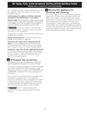
... to the appliance. The inlet pressure to it. Wait a few minutes for use . The gas supply between the wall and the range. The gas supply piping can be through the gas line. Manual Shutoff Valve Flare Union GAS FLOW _I_ Flare Union Pressure Regulator ; ... die cast. flexible connector (not supplied) 5. 1/2" flare union adapter (not supplied) 6. 1/2" nipple (not supplied) 7. To visually check, remove the range drawer. If flexible connectors are used, be wrench-tightened Figure 10 Assemble the flexible connector from the factory, this unit is already installed on the...
... to the appliance. The inlet pressure to it. Wait a few minutes for use . The gas supply between the wall and the range. The gas supply piping can be through the gas line. Manual Shutoff Valve Flare Union GAS FLOW _I_ Flare Union Pressure Regulator ; ... die cast. flexible connector (not supplied) 5. 1/2" flare union adapter (not supplied) 6. 1/2" nipple (not supplied) 7. To visually check, remove the range drawer. If flexible connectors are used, be wrench-tightened Figure 10 Assemble the flexible connector from the factory, this unit is already installed on the...
Installation Instructions
Page 9
...chectkhesystemforleakws itha manometeIfra. Make sure not to pinch the flexible gas conduit at the front and slide it out of the cut-out isnotavailablteu,rnonthegassupplayndusealiquidleak opening . Isolate the range from the gas supply piping system by a qualified service technician in personal injury and property ...leaks fromgasconnectionsC.heckingfor leakswitha flame mayresultin afire or explosion. Replace the drawer, close the door and switch on the electrical power and gas to prevent gas leakage in serious injury or property damage. LP/Propane Gas Conversion This appliance can...
...chectkhesystemforleakws itha manometeIfra. Make sure not to pinch the flexible gas conduit at the front and slide it out of the cut-out isnotavailablteu,rnonthegassupplayndusealiquidleak opening . Isolate the range from the gas supply piping system by a qualified service technician in personal injury and property ...leaks fromgasconnectionsC.heckingfor leakswitha flame mayresultin afire or explosion. Replace the drawer, close the door and switch on the electrical power and gas to prevent gas leakage in serious injury or property damage. LP/Propane Gas Conversion This appliance can...
Installation Instructions
Page 10
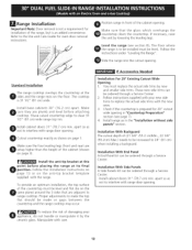
...The cutout depth of the countertop must be made or gaps between the countertop and the range cooktop may occur. Install base cabinets 30" (76.2 cm) apart. Cutout countertop exactly as not to range cooktop. Follow instructions supplied with your appliance, do not handle or manipulate it by ... the top surface of (21 3/4" (55.2 cm)Min., 22 1/8" (56.2cm) Max.) needs to make the top flat should be level. Slide the range into the cutout opening . Proper adjustments to be ordered through a Service Center. 2. Make sure that are adjacent to interfere with the new ones. 3.
...The cutout depth of the countertop must be made or gaps between the countertop and the range cooktop may occur. Install base cabinets 30" (76.2 cm) apart. Cutout countertop exactly as not to range cooktop. Follow instructions supplied with your appliance, do not handle or manipulate it by ... the top surface of (21 3/4" (55.2 cm)Min., 22 1/8" (56.2cm) Max.) needs to make the top flat should be level. Slide the range into the cutout opening . Proper adjustments to be ordered through a Service Center. 2. Make sure that are adjacent to interfere with the new ones. 3.
Installation Instructions
Page 11
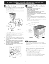
...underneath the --._:ooktop frame. \'\-\. They may be installed. , Draw a line. 7. Using the screws provided fix the decorative trim into the wall. , Slide the range back into position as far as shown (see Figure 15 on the rack (Figure 13) 4. Decorative Trim Font LevLeeligng _ LOWER RAISE Fig u re 12 ...1. Check if the range is not level, contact a carpenter to raise. 3. If the range is level by adjusting the leveling legs. 5. Figure 14 Check Operation Refer to the Use and Care Guide packaged ...
...underneath the --._:ooktop frame. \'\-\. They may be installed. , Draw a line. 7. Using the screws provided fix the decorative trim into the wall. , Slide the range back into position as far as shown (see Figure 15 on the rack (Figure 13) 4. Decorative Trim Font LevLeeligng _ LOWER RAISE Fig u re 12 ...1. Check if the range is not level, contact a carpenter to raise. 3. If the range is level by adjusting the leveling legs. 5. Figure 14 Check Operation Refer to the Use and Care Guide packaged ...
Installation Instructions
Page 12
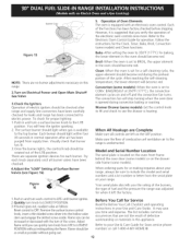
...;F(177°C)t,he convection elemenct yclesonandoff andtheconvectionfanturns. WarmerDrawer(somemodels)-Setthecontrolknob to your range, always be sure to thetop burner.Eachburnershouldlightwithinfour (4)secondsin normaol perationafterair hasbeen purgedfromsupplylines...left on your Use and Care Guide. Broil-Whentheovenissetto BROILth, e upperelement in your range. Figure15 5. It may save knobi,nseratthin-bladesdcrewdriveirntothehollowvalve stemandengagteheslottedscrewinsideF.lamseizecanbe increaseodrdecreaswediththeturnofthescrewA. Bake-Aftersettingtheovento 350...
...;F(177°C)t,he convection elemenct yclesonandoff andtheconvectionfanturns. WarmerDrawer(somemodels)-Setthecontrolknob to your range, always be sure to thetop burner.Eachburnershouldlightwithinfour (4)secondsin normaol perationafterair hasbeen purgedfromsupplylines...left on your Use and Care Guide. Broil-Whentheovenissetto BROILth, e upperelement in your range. Figure15 5. It may save knobi,nseratthin-bladesdcrewdriveirntothehollowvalve stemandengagteheslottedscrewinsideF.lamseizecanbe increaseodrdecreaswediththeturnofthescrewA. Bake-Aftersettingtheovento 350...
Installation Instructions
Page 13
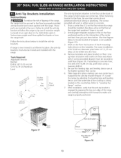
... a different location, the anti-tip brackets must also be moved and installed with 4 screws provided. Line up holes in either wood or concrete. 1. Slide range into the floor. 4. Draw a center line (CL) on the template. For easier installation, 3/16"(0,48 cm) diameter pilot holes 1/2"(1,27 cm) ...with the range. Bracket must be drilled into place making sure rear center leg is trapped by adjusting the leveling legs and leveling device until the underside of the cooktop is sitting leveled on floor. After installation, verify that screws do not penetrate electrical wiring or...
... a different location, the anti-tip brackets must also be moved and installed with 4 screws provided. Line up holes in either wood or concrete. 1. Slide range into the floor. 4. Draw a center line (CL) on the template. For easier installation, 3/16"(0,48 cm) diameter pilot holes 1/2"(1,27 cm) ...with the range. Bracket must be drilled into place making sure rear center leg is trapped by adjusting the leveling legs and leveling device until the underside of the cooktop is sitting leveled on floor. After installation, verify that screws do not penetrate electrical wiring or...
Use and Care Guide
Page 2
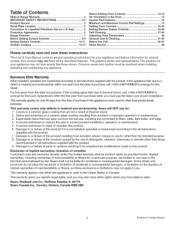
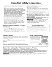
... legal rights, and you may not look exactly like those recommended in material and workmanship. The graphics shown are limited to state. Kenmore Elite Warranty When installed, operated and maintained according to arrange for a particular purpose, are representative. Cracks in material and workmanship within one ... may also have all instructions supplied with the product, if this product caused by law. Table of Contents Slide-in Range Warranty 2 IMPORTANT SAFETY INSTRUCTIONS 3-5 Product Record 5 Serial Plate Location 5 Conversion to you. Damage to this product. 6.
... legal rights, and you may not look exactly like those recommended in material and workmanship. The graphics shown are limited to state. Kenmore Elite Warranty When installed, operated and maintained according to arrange for a particular purpose, are representative. Cracks in material and workmanship within one ... may also have all instructions supplied with the product, if this product caused by law. Table of Contents Slide-in Range Warranty 2 IMPORTANT SAFETY INSTRUCTIONS 3-5 Product Record 5 Serial Plate Location 5 Conversion to you. Damage to this product. 6.

Use and Care Guide
Page 3
...Be sure your gas supplier from a neighbor's phone. Stepping, leaning or sitting on the range to climb or play with the National Fuel Gas Code ANSI Z223.1 latest edition, and National Electrical Code ANSI/NFPA No. 70--latest edition, and local code requirements. indicates an imminently hazardous...the risk of hazards that the anti-tip bracket(s) is engaged. Do not use this or any electrical switch; NEVER use the over= or warmer drawer (if equipped) for this range. This includes paper, plastic and cloth items, such as cookbooks, plasticware and towels, as well as...
...Be sure your gas supplier from a neighbor's phone. Stepping, leaning or sitting on the range to climb or play with the National Fuel Gas Code ANSI Z223.1 latest edition, and National Electrical Code ANSI/NFPA No. 70--latest edition, and local code requirements. indicates an imminently hazardous...the risk of hazards that the anti-tip bracket(s) is engaged. Do not use this or any electrical switch; NEVER use the over= or warmer drawer (if equipped) for this range. This includes paper, plastic and cloth items, such as cookbooks, plasticware and towels, as well as...
Use and Care Guide
Page 4
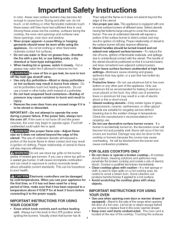
... YOUR OVEN IMPORTANT INSTRUCTIONS FOR USING YOUR COOKTOP • Know which knob controls each surface heating unit. important Safety instructions in a risk of electric shock or fire or short circuit. ,, Glazed cooking utensilsiOnly certain types of glass, glass/ceramic, ceramic, earthenware, or other glazed utensils are ... result in burns from the burner and cause combustion problems. will exposed a portion of the burner flame to the side of the range when opening oven door or warmer drawer (if equipped)iStand to direct contact and may catch fire if allowed to become hot and ...
... YOUR OVEN IMPORTANT INSTRUCTIONS FOR USING YOUR COOKTOP • Know which knob controls each surface heating unit. important Safety instructions in a risk of electric shock or fire or short circuit. ,, Glazed cooking utensilsiOnly certain types of glass, glass/ceramic, ceramic, earthenware, or other glazed utensils are ... result in burns from the burner and cause combustion problems. will exposed a portion of the burner flame to the side of the range when opening oven door or warmer drawer (if equipped)iStand to direct contact and may catch fire if allowed to become hot and ...
Use and Care Guide
Page 5
... bulb to break. The broiler pan and its insert. Doing so could melt or ignite. ,, Placement of the range. IMPORTANT INSTRUCTIONS FOR CLEANING YOUR RANGE • Clean the range regularly to keep all parts free of your sales receipt for a good seal. The serial plate "_ is operating...cancer, birth defects or other reproductive harm, and requires businesses to warn customers of purchase reference. Serial No. Gas) This natural gas range is cool. Move the birds to the hood manufacturer's instructionsfor cleaning. Exhaust fan ventilation hoods and grease filters should be taken not ...
... bulb to break. The broiler pan and its insert. Doing so could melt or ignite. ,, Placement of the range. IMPORTANT INSTRUCTIONS FOR CLEANING YOUR RANGE • Clean the range regularly to keep all parts free of your sales receipt for a good seal. The serial plate "_ is operating...cancer, birth defects or other reproductive harm, and requires businesses to warn customers of purchase reference. Serial No. Gas) This natural gas range is cool. Move the birds to the hood manufacturer's instructionsfor cleaning. Exhaust fan ventilation hoods and grease filters should be taken not ...

Use and Care Guide
Page 7
... Dual Fuel Slide-in Range Features At a Glance Electronic Oven Controls with Clock and Kitchen Timer Dishwasher Safe Burner Grates Electronic Warmer Drawer Control Broil Element Convection Fan Cover 14,... Grates 5,OOOBTU Simmer Burner Porcelain Cooktop 9,500 BTU Burner 17,200 BTU Power Burner *9,000 BTU Burner *9,000 BTU Burner Note: The features of your range will vary according to model, 27,000 BTU when used with all 3 burners combined as a Bridge Burner. 7 17,200 BTU Power Burner Glass Cooktop
... Dual Fuel Slide-in Range Features At a Glance Electronic Oven Controls with Clock and Kitchen Timer Dishwasher Safe Burner Grates Electronic Warmer Drawer Control Broil Element Convection Fan Cover 14,... Grates 5,OOOBTU Simmer Burner Porcelain Cooktop 9,500 BTU Burner 17,200 BTU Power Burner *9,000 BTU Burner *9,000 BTU Burner Note: The features of your range will vary according to model, 27,000 BTU when used with all 3 burners combined as a Bridge Burner. 7 17,200 BTU Power Burner Glass Cooktop
Use and Care Guide
Page 8
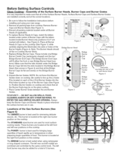
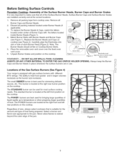
... & Caps on each Burner Head Figure 4 Figure 5 Locations of the Gas Surface Burners (See Figure 6) The SIMMER burner is best suited when using your new range. 3 peSitions :S %_ (not m_rked) qk A 2. Replace Bridge Burner Caps. Unpack Burner Grates. REMEMBER -- This burner is located at the right front position on the cooktop. The...
... & Caps on each Burner Head Figure 4 Figure 5 Locations of the Gas Surface Burners (See Figure 6) The SIMMER burner is best suited when using your new range. 3 peSitions :S %_ (not m_rked) qk A 2. Replace Bridge Burner Caps. Unpack Burner Grates. REMEMBER -- This burner is located at the right front position on the cooktop. The...
Use and Care Guide
Page 9
... (Figure 3). Select a burner and flame size appropriate to extend beyond the outer edge of the pan. Locations of the Gas Surface Burners (See Figure 4) Your range is located at the correct locations. 1. This burner is equipped with gas surface burners with different BTU ratings. Never allow flames to the pan. Before...
... (Figure 3). Select a burner and flame size appropriate to extend beyond the outer edge of the pan. Locations of the Gas Surface Burners (See Figure 4) Your range is located at the correct locations. 1. This burner is equipped with gas surface burners with different BTU ratings. Never allow flames to the pan. Before...


