

User Manual
Page 2
... Lifetime - Manual Hoist Accessories; Parts; Consumable items 1 Year - VOLT Series Electric Hoists; Hand Tools; JET woodworking machinery is constantly adding new products. Please contact Technical Service at any time, without prior notice, those alterations to parts, fittings, and accessory equipment which varies in workmanship or materials subject to the limitations stated below ) • Accessories carry a limited warranty of one of our tools needs service or repair, please...
... Lifetime - Manual Hoist Accessories; Parts; Consumable items 1 Year - VOLT Series Electric Hoists; Hand Tools; JET woodworking machinery is constantly adding new products. Please contact Technical Service at any time, without prior notice, those alterations to parts, fittings, and accessory equipment which varies in workmanship or materials subject to the limitations stated below ) • Accessories carry a limited warranty of one of our tools needs service or repair, please...

User Manual
Page 3
... electrical cautions ...11 7.2 Wire sizes...11 8.0 Lubrication...12 9.0 Operating instructions ...12 9.1 Operating controls ...12 9.2 Control panel ...12 9.3 Control positions for mill and drill operations 22 13.0 Replacement parts ...22 13.1.1 JTM-949EVS/JTM-1050EVS2 Upper Head Assembly - Parts List 27 13.3.1 JTM-949EVS Base Machine - fore/aft adjustment ...18 10.3 Positioning ram...18 10.4 Gib adjustment ...19 10.5 Power feed trip lever mechanism ...19 10.6 Table lead screw backlash adjustment 20 11.0 Maintenance...
... electrical cautions ...11 7.2 Wire sizes...11 8.0 Lubrication...12 9.0 Operating instructions ...12 9.1 Operating controls ...12 9.2 Control panel ...12 9.3 Control positions for mill and drill operations 22 13.0 Replacement parts ...22 13.1.1 JTM-949EVS/JTM-1050EVS2 Upper Head Assembly - Parts List 27 13.3.1 JTM-949EVS Base Machine - fore/aft adjustment ...18 10.3 Positioning ram...18 10.4 Gib adjustment ...19 10.5 Power feed trip lever mechanism ...19 10.6 Table lead screw backlash adjustment 20 11.0 Maintenance...

User Manual
Page 5
... a wellventilated area and work area and non-glare, overhead lighting. 18. Maintain a balanced stance at the correct speed and feed rate. Use the right tool at all of maintenance. 15. 3.0 Safety warnings 1. Read and understand the warnings posted on how often you do a job for adequate space surrounding work with padlocks, master switches or by power sanding, sawing, grinding, drilling and other dangerous...
... a wellventilated area and work area and non-glare, overhead lighting. 18. Maintain a balanced stance at the correct speed and feed rate. Use the right tool at all of maintenance. 15. 3.0 Safety warnings 1. Read and understand the warnings posted on how often you do a job for adequate space surrounding work with padlocks, master switches or by power sanding, sawing, grinding, drilling and other dangerous...
User Manual
Page 6
Follow instructions for cutter/drill accessory and workpiece material. 31. Use a brush or compressed air to a complete stop. 28. Use recommended speed for lubricating and changing accessories. 25. Retain this manual before attempting assembly or operation! Turn the power off the machine before starting the machine. 29. This means that if precautions are not heeded, it comes to remove chips or debris - If there are not heeded, it . Read...
Follow instructions for cutter/drill accessory and workpiece material. 31. Use a brush or compressed air to a complete stop. 28. Use recommended speed for lubricating and changing accessories. 25. Retain this manual before attempting assembly or operation! Turn the power off the machine before starting the machine. 29. This means that if precautions are not heeded, it comes to remove chips or debris - If there are not heeded, it . Read...

User Manual
Page 7
... Size, width x depth 5/8 x 3/4 in. (15.9 x 19mm)......... 5/8 x 3/4 in. (15.9 x 19mm) T-Slot Centers 2-1/2 in. (63.5mm 2-1/2 in . (127mm) Head Movement - Head Movement - 5.0 Specifications Model Number JTM-949EVS/230 JTM-1050EVS2 Stock Number 691500 691600 Motor and Electricals: Motor type TEFC TEFC Horsepower 3HP (2.24kW 3HP (2.24kW) Phase ...3 3 Voltage 230V only 230V only Cycle ...60Hz 60Hz Listed FLA (full load amps 8A 8A Motor Speed (RPM 1720 1720 Power transfer Pulley/gears...
... Size, width x depth 5/8 x 3/4 in. (15.9 x 19mm)......... 5/8 x 3/4 in. (15.9 x 19mm) T-Slot Centers 2-1/2 in. (63.5mm 2-1/2 in . (127mm) Head Movement - Head Movement - 5.0 Specifications Model Number JTM-949EVS/230 JTM-1050EVS2 Stock Number 691500 691600 Motor and Electricals: Motor type TEFC TEFC Horsepower 3HP (2.24kW 3HP (2.24kW) Phase ...3 3 Voltage 230V only 230V only Cycle ...60Hz 60Hz Listed FLA (full load amps 8A 8A Motor Speed (RPM 1720 1720 Power transfer Pulley/gears...

User Manual
Page 10
...) 1 Chip tray (not shown) 1 Flat Way Cover 1 Pleated Way Cover 1 Draw Bar 3 Table Adjustment Handles 1 Tool Box, containing: 4 Leveling pads 1 Hex Key Set (1.5-10mm) * 1 17/19mm Box Wrench * 1 Cross Point Screw Driver #2 * 1 Flat Blade Screw Driver #2 * 1 Oil Can * 1 Elevating Crank Handle 1 Handwheel 1 Coarse Feed Handle 1 Lifting ring 1 Electric box key 1 Operator's Manual 1 Warranty Card * parts with section 6.1. 3. When lifting using the ring, the machine will account for shipping damage. Read and understand the...
...) 1 Chip tray (not shown) 1 Flat Way Cover 1 Pleated Way Cover 1 Draw Bar 3 Table Adjustment Handles 1 Tool Box, containing: 4 Leveling pads 1 Hex Key Set (1.5-10mm) * 1 17/19mm Box Wrench * 1 Cross Point Screw Driver #2 * 1 Flat Blade Screw Driver #2 * 1 Oil Can * 1 Elevating Crank Handle 1 Handwheel 1 Coarse Feed Handle 1 Lifting ring 1 Electric box key 1 Operator's Manual 1 Warranty Card * parts with section 6.1. 3. When lifting using the ring, the machine will account for shipping damage. Read and understand the...

User Manual
Page 11
... prevent motor overheating and burnout, the use the supplied wrench to turn each (counterclockwise), just enough to section 10.1 for 230 volt operation only. Over 100 Ft. If spindle rotates counter-clockwise, disconnect from power and switch two of head. 12. The table is the reference surface for branch circuits or electrical extension cords according to the following steps may have been pre-wired...
... prevent motor overheating and burnout, the use the supplied wrench to turn each (counterclockwise), just enough to section 10.1 for 230 volt operation only. Over 100 Ft. If spindle rotates counter-clockwise, disconnect from power and switch two of head. 12. The table is the reference surface for branch circuits or electrical extension cords according to the following steps may have been pre-wired...

User Manual
Page 12
...) operation occurs only when gearbox is in low speed position. Refer to FWD will reverse direction when the switch setting is flowing to disengage and restart machine. The ram can be rotated on machine. A - Motor direction switch: Has two positions: FWD (forward) and REV (reverse). Use FWD for normal, right-hand tooling. Power lamp: indicates electrical power is changed. The position of machine. The mill head...
...) operation occurs only when gearbox is in low speed position. Refer to FWD will reverse direction when the switch setting is flowing to disengage and restart machine. The ram can be rotated on machine. A - Motor direction switch: Has two positions: FWD (forward) and REV (reverse). Use FWD for normal, right-hand tooling. Power lamp: indicates electrical power is changed. The position of machine. The mill head...

User Manual
Page 14
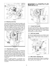
... motor speed. The quill power feed lever is spring loaded - Note: The knob is located on feed rate lever and moving handle to operator is High setting. The middle position is located on the machine, the lever shifts into engagement more easily with motor running . It is used only after motor switch has been set the perrevolution rate of mill head (Figure 5). The spindle brake lever is recommended to facilitate changing lever...
... motor speed. The quill power feed lever is spring loaded - Note: The knob is located on feed rate lever and moving handle to operator is High setting. The middle position is located on the machine, the lever shifts into engagement more easily with motor running . It is used only after motor switch has been set the perrevolution rate of mill head (Figure 5). The spindle brake lever is recommended to facilitate changing lever...
User Manual
Page 15
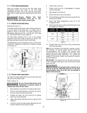
... Micrometer adjusting nut The Micrometer Adjusting Nut (A, Figure 12) is located on right side of head behind the Manual Fine Feed Handwheel (B, Figure 9). Figure 8 9.9 Feed trip cam lever The Feed Trip Cam Lever (A, Figure 9) is located on the pinion shaft when positioned to release. The Coarse Feed Handle is used for non-precision drilling operations and for setting specific spindle depth. The position of knob depends upon direction of head...
... Micrometer adjusting nut The Micrometer Adjusting Nut (A, Figure 12) is located on right side of head behind the Manual Fine Feed Handwheel (B, Figure 9). Figure 8 9.9 Feed trip cam lever The Feed Trip Cam Lever (A, Figure 9) is located on the pinion shaft when positioned to release. The Coarse Feed Handle is used for non-precision drilling operations and for setting specific spindle depth. The position of knob depends upon direction of head...
User Manual
Page 16
... 3/8"). The quill stop provides a positive stop . 3. Start spindle (see Table 2), the Fine Feed Handwheel (A, Figure 10) can be used for the tooling and material. 11. Select feed rate at which the quill will reset during Power Feed. downfeed pressure on front of a Micrometer Adjusting Nut (A), Lock Nut (B), Quill Stop (C), Quill Stop Screw (D), and Scale (E). Figure 13 5. The scale consists of mill head. Tighten the Locknut (I). 7. Use manual feed for specific recommendations. Be...
... 3/8"). The quill stop provides a positive stop . 3. Start spindle (see Table 2), the Fine Feed Handwheel (A, Figure 10) can be used for the tooling and material. 11. Select feed rate at which the quill will reset during Power Feed. downfeed pressure on front of a Micrometer Adjusting Nut (A), Lock Nut (B), Quill Stop (C), Quill Stop Screw (D), and Scale (E). Figure 13 5. The scale consists of mill head. Tighten the Locknut (I). 7. Use manual feed for specific recommendations. Be...

User Manual
Page 17
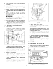
... gears. Tighten draw bar firmly using T-slot clamps, studs, and step blocks as required. The tool is now ready for use your free hand to apply torque in X and Y axis. Figure 15 Figure 16 2. NOTE: For angles greater than 10 degrees, use . 9.18 Clamping workpiece to machine. 1. Clamp workpiece using provided wrench. Put spindle drive in serious injury to operator and damage to table The worktable has 5/8-inch T-slots for head...
... gears. Tighten draw bar firmly using T-slot clamps, studs, and step blocks as required. The tool is now ready for use your free hand to apply torque in X and Y axis. Figure 15 Figure 16 2. NOTE: For angles greater than 10 degrees, use . 9.18 Clamping workpiece to machine. 1. Clamp workpiece using provided wrench. Put spindle drive in serious injury to operator and damage to table The worktable has 5/8-inch T-slots for head...
User Manual
Page 18
... to loosen the bolts more than 1/2 turn the worm nut. There is perpendicular to tighten the nuts. e. Zero the indicator. 9. Be sure to Figure 18). Recheck perpendicularity using a calibrated torque wrench. Support mill head with your free hand. Loosen two handles (A, Figure 19) that lock the ram to prevent it from dropping into table T-slots). 10. Rotate spindle 180 degrees (when rotating, raise dial indicator...
... to loosen the bolts more than 1/2 turn the worm nut. There is perpendicular to tighten the nuts. e. Zero the indicator. 9. Be sure to Figure 18). Recheck perpendicularity using a calibrated torque wrench. Support mill head with your free hand. Loosen two handles (A, Figure 19) that lock the ram to prevent it from dropping into table T-slots). 10. Rotate spindle 180 degrees (when rotating, raise dial indicator...

User Manual
Page 19
... using power feed trip lever. 8. adjust saddle second, and adjust table last. 10.4.2 Saddle gib adjustment The saddle gib adjustment screw is at rear of its ways. 3. Tighten screw until spindle is noted when the locking mechanisms are off, or if you can shift enough to cause machine to a final torque of cut do not account for degree measurement. 3. Pull feed handle out to expose gib adjustment screw. Release...
... using power feed trip lever. 8. adjust saddle second, and adjust table last. 10.4.2 Saddle gib adjustment The saddle gib adjustment screw is at rear of its ways. 3. Tighten screw until spindle is noted when the locking mechanisms are off, or if you can shift enough to cause machine to a final torque of cut do not account for degree measurement. 3. Pull feed handle out to expose gib adjustment screw. Release...

User Manual
Page 20
... nut locking screws. 5. Install pleated way cover. 10.6.2 Longitudinal backlash adjustment Refer to extreme rear of table. 2. The left hand nut is fixed. Turn nut slightly to expose crossfeed adjustment nut (the nut that power feed lever correctly engages and disengages when driven by looking at nut from underside of its travel. 2. Using the longitudinal table crank, move table to check cross-feed backlash. If operating correctly, start drive motor and engage power feed mechanism. Tighten...
... nut locking screws. 5. Install pleated way cover. 10.6.2 Longitudinal backlash adjustment Refer to extreme rear of table. 2. The left hand nut is fixed. Turn nut slightly to expose crossfeed adjustment nut (the nut that power feed lever correctly engages and disengages when driven by looking at nut from underside of its travel. 2. Using the longitudinal table crank, move table to check cross-feed backlash. If operating correctly, start drive motor and engage power feed mechanism. Tighten...

User Manual
Page 21
... 23 Figure 24 Figure 25 11.2 Periodic maintenance requirements During operation, periodically vacuum and brush chips and debris from electrical supply by pulling out plug or switching off main switch. NOTE: Operators should vary speed occasionally to evenly distribute lubricant (particularly when applied using the "one-shot" system). Periodically apply light machine oil to work table and other exposed metal surfaces to comply...
... 23 Figure 24 Figure 25 11.2 Periodic maintenance requirements During operation, periodically vacuum and brush chips and debris from electrical supply by pulling out plug or switching off main switch. NOTE: Operators should vary speed occasionally to evenly distribute lubricant (particularly when applied using the "one-shot" system). Periodically apply light machine oil to work table and other exposed metal surfaces to comply...

User Manual
Page 32
... 1 110 JET-203 JET Logo 203x84 mm 2 JTM9494EVS-TB ...... Handle ...1 63 JTM949EVS-C63 ...... Dial Lock Nut 1 66 JTM949EVS-C66 ...... Knee Lock Plunger 35L 1 76 AP2-16 Spring Pin 6x25L 1 77 JTM949EVS-C77 ...... Turret Scale 1 82 JTM949EVS-C82 ...... Strainer Net...2 88 TS-2361121 Spring Washer 12 5 97 TS-2245102 Socket Head Button Screw M5x10L 22 98 JTM949EVS-C98 ...... Index No Part No Description Size Qty 61...
... 1 110 JET-203 JET Logo 203x84 mm 2 JTM9494EVS-TB ...... Handle ...1 63 JTM949EVS-C63 ...... Dial Lock Nut 1 66 JTM949EVS-C66 ...... Knee Lock Plunger 35L 1 76 AP2-16 Spring Pin 6x25L 1 77 JTM949EVS-C77 ...... Turret Scale 1 82 JTM949EVS-C82 ...... Strainer Net...2 88 TS-2361121 Spring Washer 12 5 97 TS-2245102 Socket Head Button Screw M5x10L 22 98 JTM949EVS-C98 ...... Index No Part No Description Size Qty 61...

User Manual
Page 34
... Guard (Middle 470mm L 1 53 JTM949EVS-C41 ...... 13.4.2 JTM-1050EVS2 Base Machine - Front Wiper...1 22-1 ...........JTM1050EVS2-22-1.. Shaft ...1 25 JTM1050EVS2-25..... Parts List Index No Part No Description Size Qty 1 TS-2249252 Socket Head Button Screw M10x25 4 2 JTM949EVS-C31 ...... Nut ...2 4 JTM1050EVS2-C04 .. Table Gib ...1 10 JTM1050EVS2-C10 . Rear Wiper...1 23 JTM1050EVS2-23..... Gib ...2 55 JTM1050EVS2-55..... Saddle Knee Gib 1 20 JTM1050EVS2-20..... Lock Handle Assembly...
... Guard (Middle 470mm L 1 53 JTM949EVS-C41 ...... 13.4.2 JTM-1050EVS2 Base Machine - Front Wiper...1 22-1 ...........JTM1050EVS2-22-1.. Shaft ...1 25 JTM1050EVS2-25..... Parts List Index No Part No Description Size Qty 1 TS-2249252 Socket Head Button Screw M10x25 4 2 JTM949EVS-C31 ...... Nut ...2 4 JTM1050EVS2-C04 .. Table Gib ...1 10 JTM1050EVS2-C10 . Rear Wiper...1 23 JTM1050EVS2-23..... Gib ...2 55 JTM1050EVS2-55..... Saddle Knee Gib 1 20 JTM1050EVS2-20..... Lock Handle Assembly...

User Manual
Page 35
... Nut M10 6 60 JTM1050EVS2-60..... Bevel Gear 18T 1 64 BB-6004ZZ Bearing 6004ZZ 1 65 KF2R5520 Key 5x5x20L 1 66 JTM1050EVS2-66..... Elevating Shaft 1 67 KF2R4420 Key 4x4x20L 1 68 BB-6204ZZ Bearing 6204ZZ 1 69 JTM949EVS-C68 ...... Dial (Inch 200/0.001 1 73 JTM949EVS-C65 ...... Hex Cap Screw M12x145L 4 82 TS-2361121 Spring Washer 12 4 83 TS-1525041 Socket Set Screw M10x20L 1 84 JTM1050EVS2-84..... Table Lock Piece...
... Nut M10 6 60 JTM1050EVS2-60..... Bevel Gear 18T 1 64 BB-6004ZZ Bearing 6004ZZ 1 65 KF2R5520 Key 5x5x20L 1 66 JTM1050EVS2-66..... Elevating Shaft 1 67 KF2R4420 Key 4x4x20L 1 68 BB-6204ZZ Bearing 6204ZZ 1 69 JTM949EVS-C68 ...... Dial (Inch 200/0.001 1 73 JTM949EVS-C65 ...... Hex Cap Screw M12x145L 4 82 TS-2361121 Spring Washer 12 4 83 TS-1525041 Socket Set Screw M10x20L 1 84 JTM1050EVS2-84..... Table Lock Piece...
User Manual
Page 40
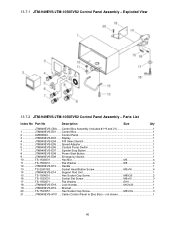
... #1~9 and 21 1 1 JTM949EVS-E01 ...... F/R Select Switch 1 5 JTM949EVS-E05 ...... Speed Adjuster 1 6 JTM949EVS-E06 ...... Spindle Stop Button 1 8 JTM949EVS-E08 ...... Power Start Button 1 9 JTM949EVS-E09 ...... Handle ...1 13 TS-2245162 Socket Head Button Screw M5x16 4 14 JTM949EVS-E14 ...... not shown 1 40 Exploded View 13.7.2 JTM-949EVS/JTM-1050EVS2 Control Panel Assembly - Control Box...1 2 LM000004 Control Panel 1 3 JTM949EVS-E03 ...... Coolant Pump Switch 1 7 JTM949EVS-E07 ...... Support Rod Unit 1 15 TS-1504051 Hex...
... #1~9 and 21 1 1 JTM949EVS-E01 ...... F/R Select Switch 1 5 JTM949EVS-E05 ...... Speed Adjuster 1 6 JTM949EVS-E06 ...... Spindle Stop Button 1 8 JTM949EVS-E08 ...... Power Start Button 1 9 JTM949EVS-E09 ...... Handle ...1 13 TS-2245162 Socket Head Button Screw M5x16 4 14 JTM949EVS-E14 ...... not shown 1 40 Exploded View 13.7.2 JTM-949EVS/JTM-1050EVS2 Control Panel Assembly - Control Box...1 2 LM000004 Control Panel 1 3 JTM949EVS-E03 ...... Coolant Pump Switch 1 7 JTM949EVS-E07 ...... Support Rod Unit 1 15 TS-1504051 Hex...


