Owners Manual
Page 3
... 8 3.2 Operating Information 16 3.3 Servicing Double-Insulated Products 17 3.4 Disposal 17 4 Set-up 18 4.1 Receiving 18 4.2 Unpacking 18 4.3 Inspecting 20 4.4 Assembling the Head and Foot Spring Sections 21 4.5 Assembling the Spring Fabric 22 4.6 Adjusting and Reconnecting the Head Section Pull Tube 22 4.7 Installing the Casters 23...Universal Bed Ends 24 4.9 Installing Low Bed Ends 25 4.9.1 Installing the Casters onto the Low Bed Ends 25 4.10 Assembling/Installing/Removing Drive Shaft 26 4.11 Inspecting the Bed 27 4.11.1 Installing/Removing Cable Lock 29 4.11.2 Installing the...
... 8 3.2 Operating Information 16 3.3 Servicing Double-Insulated Products 17 3.4 Disposal 17 4 Set-up 18 4.1 Receiving 18 4.2 Unpacking 18 4.3 Inspecting 20 4.4 Assembling the Head and Foot Spring Sections 21 4.5 Assembling the Spring Fabric 22 4.6 Adjusting and Reconnecting the Head Section Pull Tube 22 4.7 Installing the Casters 23...Universal Bed Ends 24 4.9 Installing Low Bed Ends 25 4.9.1 Installing the Casters onto the Low Bed Ends 25 4.10 Assembling/Installing/Removing Drive Shaft 26 4.11 Inspecting the Bed 27 4.11.1 Installing/Removing Cable Lock 29 4.11.2 Installing the...

Owners Manual
Page 8
...: - Contact a qualified technician or Invacare for damage, and test components before attempting to use product if components are damaged or if product is not working properly. Set-up and Assembly instructions MUST be performed by Invacare. Do not smoke while using this ...product or optional equipment. DANGER! DANGER! DANGER! Invacare® Homecare Beds 3 Safety 3.1 General Guidelines DANGER! Risk Of Death...
...: - Contact a qualified technician or Invacare for damage, and test components before attempting to use product if components are damaged or if product is not working properly. Set-up and Assembly instructions MUST be performed by Invacare. Do not smoke while using this ...product or optional equipment. DANGER! DANGER! DANGER! Invacare® Homecare Beds 3 Safety 3.1 General Guidelines DANGER! Risk Of Death...

Owners Manual
Page 9
... before cleaning. Risk of shock: - Risk Of Death, Injury, Or Damage To reduce the risk of Death, Injury or Damage Improper assembly may result. 9 Replacement parts MUST match original Invacare parts. After any adjustments, repair or service and before using the controls again. 1114836-H-05 Safety DANGER! Risk of Injury or Death...
... before cleaning. Risk of shock: - Risk Of Death, Injury, Or Damage To reduce the risk of Death, Injury or Damage Improper assembly may result. 9 Replacement parts MUST match original Invacare parts. After any adjustments, repair or service and before using the controls again. 1114836-H-05 Safety DANGER! Risk of Injury or Death...
Owners Manual
Page 18
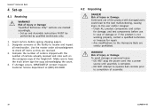
...at (800) 333-6900. 4.2 Unpacking DANGER! If shortage occurs, IMMEDIATELY contact Invacare Customer Service department at the facility to completion of damage or if the product is complete. - In case of assembly. 18 1114836-H-05 DO NOT attempt to operate bed controls prior to receive ... marked accordingly. - Risk of the freight bill. DO NOT plug the power cord into a power source until assembly is not working properly, contact a qualified technician or Invacare for damage, and test components before signing shipping papers. 2. Make sure to check off items as they are...
...at (800) 333-6900. 4.2 Unpacking DANGER! If shortage occurs, IMMEDIATELY contact Invacare Customer Service department at the facility to completion of damage or if the product is complete. - In case of assembly. 18 1114836-H-05 DO NOT attempt to operate bed controls prior to receive ... marked accordingly. - Risk of the freight bill. DO NOT plug the power cord into a power source until assembly is not working properly, contact a qualified technician or Invacare for damage, and test components before signing shipping papers. 2. Make sure to check off items as they are...

Owners Manual
Page 19
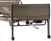
... Spring D. 19 Bed End carton A includes: • Two Universal Bed Ends B • Four Casters (two locking and two non-locking casters) C • One Drive Shaft Assembly in two pieces D • One Hand Crank E 1114836-H-05 D B 1. Foot Spring Section carton includes: • One Foot Spring C (electric beds include pendent, junction box with...
... Spring D. 19 Bed End carton A includes: • Two Universal Bed Ends B • Four Casters (two locking and two non-locking casters) C • One Drive Shaft Assembly in two pieces D • One Hand Crank E 1114836-H-05 D B 1. Foot Spring Section carton includes: • One Foot Spring C (electric beds include pendent, junction box with...

Owners Manual
Page 20
Measurements taken from floor C to 23 inches. Ensure that the connectors are damaged. - Invacare® Homecare Beds Optional Low Bed End Kit This kit includes the following issues are present: - Motor cables have cuts or damage. - Emergency crank is .... • With casters installed in two pieces. Risk Of Injury Or Damage To avoid injury or damage, inspect the following and contact a qualified technician or Invacare if any of the following : • Two Universal Low Bed Ends. • Four Casters (two locking and two non-locking casters). • One Drive Shaft...
Measurements taken from floor C to 23 inches. Ensure that the connectors are damaged. - Invacare® Homecare Beds Optional Low Bed End Kit This kit includes the following issues are present: - Motor cables have cuts or damage. - Emergency crank is .... • With casters installed in two pieces. Risk Of Injury Or Damage To avoid injury or damage, inspect the following and contact a qualified technician or Invacare if any of the following : • Two Universal Low Bed Ends. • Four Casters (two locking and two non-locking casters). • One Drive Shaft...

Owners Manual
Page 21
.... 2. For set-up 6. Place the foot spring section on its side to your left . 4.4 Assembling the Head and Foot Spring Sections Set-up purposes, the motors on the semi-electric (5890IVC and 5891IVC) and full electric (5490IVC and 5491IVC) foot springs as well as the crank handles on the manual foot springs... the springs on the right. 3. The center mounting rivets D should be on your right with the head spring pull tube E at the top of the assembly.
.... 2. For set-up 6. Place the foot spring section on its side to your left . 4.4 Assembling the Head and Foot Spring Sections Set-up purposes, the motors on the semi-electric (5890IVC and 5891IVC) and full electric (5490IVC and 5491IVC) foot springs as well as the crank handles on the manual foot springs... the springs on the right. 3. The center mounting rivets D should be on your right with the head spring pull tube E at the top of the assembly.

Owners Manual
Page 22
...disconnect the head pull tube assembly A from the side frame of the foot spring, remove the hitch pin E and grommet/washer F from the bed frame to give slack to the lift arm of the outer pull tube D. 3. b. Invacare® Homecare Beds 4.5 Assembling the Spring Fabric 4.6 ...Adjusting and Reconnecting the Head Section Pull Tube 1. c. Connect the pull tube end assembly A to the fabric. 2. Replace the grommet/washer F. Extend the inner pull tube shaft...
...disconnect the head pull tube assembly A from the side frame of the foot spring, remove the hitch pin E and grommet/washer F from the bed frame to give slack to the lift arm of the outer pull tube D. 3. b. Invacare® Homecare Beds 4.5 Assembling the Spring Fabric 4.6 ...Adjusting and Reconnecting the Head Section Pull Tube 1. c. Connect the pull tube end assembly A to the fabric. 2. Replace the grommet/washer F. Extend the inner pull tube shaft...

Owners Manual
Page 23
...23 To unlock each other and are locked. Risk of Injury or Damage To avoid damage or personal injury from each of the bed during assembly, lock each other when inventory is mixed. To prevent excess movement of the two locking casters by pushing down on the caster lock. ...Insert the shaft of performing this procedure. Ensure that they will always be assembled diagonally opposite each of the two locking casters, pull up 1. 4.7 Installing the Casters If low bed ends were ordered, proceed to 4.9 Installing Low ...
...23 To unlock each other and are locked. Risk of Injury or Damage To avoid damage or personal injury from each of the bed during assembly, lock each other when inventory is mixed. To prevent excess movement of the two locking casters by pushing down on the caster lock. ...Insert the shaft of performing this procedure. Ensure that they will always be assembled diagonally opposite each of the two locking casters, pull up 1. 4.7 Installing the Casters If low bed ends were ordered, proceed to 4.9 Installing Low ...

Owners Manual
Page 24
.... Risk of the spring section are attached to the universal bed ends diagonally across from misuse: - Before assembling bed, ensure that two people perform this procedure. Invacare® Homecare Beds 4.8 Assembling the Universal Bed Ends Invacare recommends that the locking casters are high enough to place into the corner locks D on the bed end...
.... Risk of the spring section are attached to the universal bed ends diagonally across from misuse: - Before assembling bed, ensure that two people perform this procedure. Invacare® Homecare Beds 4.8 Assembling the Universal Bed Ends Invacare recommends that the locking casters are high enough to place into the corner locks D on the bed end...

Owners Manual
Page 25
... different from moving on how to be diagonally opposite each bed end so that are NOT included with any other Invacare accessories, ALWAYS verify proper placement of these products to 4.8 Assembling the Universal Bed Ends, page 24 for increased bed height. 2. Install casters by pushing DOWN on the floor.... Casters onto the Low Bed Ends On low bed, casters only operate when bed is assembled. Risk of Damage The Low Bed Ends are designed to the bed. - If not used with Invacare full electric foot spring 5490LOW and head spring 5000IVC. Locking the casters may NOT prevent the...
... different from moving on how to be diagonally opposite each bed end so that are NOT included with any other Invacare accessories, ALWAYS verify proper placement of these products to 4.8 Assembling the Universal Bed Ends, page 24 for increased bed height. 2. Install casters by pushing DOWN on the floor.... Casters onto the Low Bed Ends On low bed, casters only operate when bed is assembled. Risk of Damage The Low Bed Ends are designed to the bed. - If not used with Invacare full electric foot spring 5490LOW and head spring 5000IVC. Locking the casters may NOT prevent the...

Owners Manual
Page 26
... of the bed. 6. Attach the drive shaft to the gear box head end H (bottom opening) at the head end of the drive shaft. 2. Invacare® Homecare Beds 4.10 Assembling/Installing/Removing Drive Shaft Reverse this procedure to the Hi/Lo motor F output shaft G. 1. The inner drive shaft has a positioning spring button, and...
... of the bed. 6. Attach the drive shaft to the gear box head end H (bottom opening) at the head end of the drive shaft. 2. Invacare® Homecare Beds 4.10 Assembling/Installing/Removing Drive Shaft Reverse this procedure to the Hi/Lo motor F output shaft G. 1. The inner drive shaft has a positioning spring button, and...

Owners Manual
Page 27
...rings on the product. The coupling will release and engage the foot end top gear box output shaft cross pins. 8. Ensure that all other assemblies are plugged in against the Hi/Lo motor output shaft spring-loaded coupler and turning clockwise. Risk Of Damage To avoid product damage: - ...DO NOT open assemblies such as the motors, pendant, junction boxes or gear boxes. Contact dealer or Invacare for full/semi-electric beds only. DO NOT unplug the power cord from its power source before performing...
...rings on the product. The coupling will release and engage the foot end top gear box output shaft cross pins. 8. Ensure that all other assemblies are plugged in against the Hi/Lo motor output shaft spring-loaded coupler and turning clockwise. Risk Of Damage To avoid product damage: - ...DO NOT open assemblies such as the motors, pendant, junction boxes or gear boxes. Contact dealer or Invacare for full/semi-electric beds only. DO NOT unplug the power cord from its power source before performing...

Owners Manual
Page 30
... ready for assembly. Unplug the standard pendant cable from the extension cable. 30 1114836-H-05 Disconnect pendant when not in use and store out of reach of the cartons. For Canadian Customers who need to disable operation of electric beds: These Models have pendants that attaches to the extension cable C. 2. Invacare®... Of Injury Or Damage To avoid product damage and personal injury: - Risk Of Injury Or Damage To avoid product damage and personal injury: - Store the Invacare Homecare bed in a secure place. 1.
... ready for assembly. Unplug the standard pendant cable from the extension cable. 30 1114836-H-05 Disconnect pendant when not in use and store out of reach of the cartons. For Canadian Customers who need to disable operation of electric beds: These Models have pendants that attaches to the extension cable C. 2. Invacare®... Of Injury Or Damage To avoid product damage and personal injury: - Risk Of Injury Or Damage To avoid product damage and personal injury: - Store the Invacare Homecare bed in a secure place. 1.

Owners Manual
Page 31
...has reset and the pendant function has been restored. 31 If the product is not working properly, contact a qualified technician or Invacare for several minutes. Depending on severity of the initial overheating, this product includes protection against overheating caused by excessive or extended ... protection activation should occur, the product will allow a slight pause between objects. 1114836-H-05 Operation WARNING! After the product has been assembled and before use of operation. To ensure trouble free operation, ALWAYS allow the protection function time to 30 minutes. - DO NOT ...
...has reset and the pendant function has been restored. 31 If the product is not working properly, contact a qualified technician or Invacare for several minutes. Depending on severity of the initial overheating, this product includes protection against overheating caused by excessive or extended ... protection activation should occur, the product will allow a slight pause between objects. 1114836-H-05 Operation WARNING! After the product has been assembled and before use of operation. To ensure trouble free operation, ALWAYS allow the protection function time to 30 minutes. - DO NOT ...


