
Service Guide
Page 9
... sécurité ...v Instrucciones de seguridad importantes v Warnings ...vii Chapter 1: Server System Contents and References 1 Server System Contents ...1 Intel® Server System SR1625UR Contents 1 Intel® Server System SR1625URSAS Contents 2 Additional Information and Software 3 Chapter 2: Server System Features 5 Server System Feature Overview 6 Server System Components 9 Intel® Light-Guided Diagnostics 10 Server Board Components 14 Configuration Jumpers 16 Front of Server System ...18 Peripheral Devices ...18 Control Panel ...19 Bezels ...23 Rear of...
... sécurité ...v Instrucciones de seguridad importantes v Warnings ...vii Chapter 1: Server System Contents and References 1 Server System Contents ...1 Intel® Server System SR1625UR Contents 1 Intel® Server System SR1625URSAS Contents 2 Additional Information and Software 3 Chapter 2: Server System Features 5 Server System Feature Overview 6 Server System Components 9 Intel® Light-Guided Diagnostics 10 Server Board Components 14 Configuration Jumpers 16 Front of Server System ...18 Peripheral Devices ...18 Control Panel ...19 Bezels ...23 Rear of...

Service Guide
Page 15
.... Removing the PCI Express* Riser Card 45 Figure 30. Configuration Jumpers 17 Figure 9. Passive SATA/SAS Midplane Components 27 Figure 16. Installing the Server System Cover 42 Figure 27. Installing an Add-In Card 47 Figure 32. Installing the Heatsink 56 Intel® Server System SR1625UR Service Guide xv List of Figures Figure 1. Installing the Memory 51 Figure...
.... Removing the PCI Express* Riser Card 45 Figure 30. Configuration Jumpers 17 Figure 9. Passive SATA/SAS Midplane Components 27 Figure 16. Installing the Server System Cover 42 Figure 27. Installing an Add-In Card 47 Figure 32. Installing the Heatsink 56 Intel® Server System SR1625UR Service Guide xv List of Figures Figure 1. Installing the Memory 51 Figure...

Service Guide
Page 21
...://www.intel.com/p/en_US/support/highlights/server/s5520ur Intel® Server System SR1625UR Quick Start User's Guide Available in the product box Spares, Parts List and Configuration Guide Available at: http://www.intel.com/p/en_US/support/highlights/server/s5520uror by using the Server Configurator Tool Available at: http://serverconfigurator.intel.com/default.aspx Intel® Server System SR1625UR Service Guide 3 Table 1. • Intel® Server Deployment Toolkit 3.0 CD • Intel® System Management...
...://www.intel.com/p/en_US/support/highlights/server/s5520ur Intel® Server System SR1625UR Quick Start User's Guide Available in the product box Spares, Parts List and Configuration Guide Available at: http://www.intel.com/p/en_US/support/highlights/server/s5520uror by using the Server Configurator Tool Available at: http://serverconfigurator.intel.com/default.aspx Intel® Server System SR1625UR Service Guide 3 Table 1. • Intel® Server Deployment Toolkit 3.0 CD • Intel® System Management...
Service Guide
Page 22
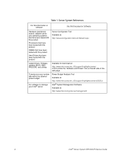
... tested with this product DIMMs that have been tested with this product Hard Drives that have been tested with this product Server Configurator Tool Available at: http://serverconfigurator.intel.com/default.aspx Latest drivers, firmware updates (BIOS, BMC, FRUSDR), and utilities Available for download at : http://www.intel.com/go/servermanagement/ 4 Intel® Server System SR1625UR Service Guide Table 1.
... tested with this product DIMMs that have been tested with this product Hard Drives that have been tested with this product Server Configurator Tool Available at: http://serverconfigurator.intel.com/default.aspx Latest drivers, firmware updates (BIOS, BMC, FRUSDR), and utilities Available for download at : http://www.intel.com/go/servermanagement/ 4 Intel® Server System SR1625UR Service Guide Table 1.

Service Guide
Page 35
... are cleared within five to ten seconds after the system is enabled. bootable recovery media with the recovery BIOS image. BIOS Recover (J1D4) If pins 2-3 are jumpered, the Integrated BMC Force Update Mode is powered on 1-2 for normal system operation. C. Configuration Jumpers Intel® Server System SR1625UR Service Guide 17 These pins should be jumpered on . BMC Force...
... are cleared within five to ten seconds after the system is enabled. bootable recovery media with the recovery BIOS image. BIOS Recover (J1D4) If pins 2-3 are jumpered, the Integrated BMC Force Update Mode is powered on 1-2 for normal system operation. C. Configuration Jumpers Intel® Server System SR1625UR Service Guide 17 These pins should be jumpered on . BMC Force...

Service Guide
Page 36
... of supported hard drives, use the Server Configurator Tool. Mini Control Panel D. Note: Drives can support: • Up to eight 2.5 inch hard drives with the mini control panel. • Up to this tool, see "Installing and Removing a Hot-swap Hard Drive" on page 3. 18 Intel® Server System SR1625UR Service Guide Drives must be specified to 17...
... of supported hard drives, use the Server Configurator Tool. Mini Control Panel D. Note: Drives can support: • Up to eight 2.5 inch hard drives with the mini control panel. • Up to this tool, see "Installing and Removing a Hot-swap Hard Drive" on page 3. 18 Intel® Server System SR1625UR Service Guide Drives must be specified to 17...

Service Guide
Page 37
... the drives provided by Intel, use the Server Configurator Tool. For a list of control panels: • Mini Control Panel • Standard Control Panel • Intel® Local Control Panel Mini Control Panel The following order codes: • Slimline DVD-ROM Drive: AXXSATADVDROM • Slimline DVD-RW Drive: AXXSATADVDRWROM Note: The Intel® Server System SR1625UR does not support...
... the drives provided by Intel, use the Server Configurator Tool. For a list of control panels: • Mini Control Panel • Standard Control Panel • Intel® Local Control Panel Mini Control Panel The following order codes: • Slimline DVD-ROM Drive: AXXSATADVDROM • Slimline DVD-RW Drive: AXXSATADVDRWROM Note: The Intel® Server System SR1625UR does not support...

Service Guide
Page 48
... remote control of which affect the ability to configure RAID. For instructions on installing the Intel® Remote Management Module 3, see "Installing the Intel® Integrated RAID Activation Key and the RAID Mini-DIMM" on page 66. 30 Intel® Server System SR1625UR Service Guide For information on installing the Intel® RAID Activation Key AXXRAKSW5 accessory to the...
... remote control of which affect the ability to configure RAID. For instructions on installing the Intel® Remote Management Module 3, see "Installing the Intel® Integrated RAID Activation Key and the RAID Mini-DIMM" on page 66. 30 Intel® Server System SR1625UR Service Guide For information on installing the Intel® RAID Activation Key AXXRAKSW5 accessory to the...

Service Guide
Page 49
...position of the rack to the top. In other words, install the first system in each rackmount option kit. Intel® Server System SR1625UR Service Guide 31 An optional cable management arm can be used with this server system into a rack: • Fixed mount relay rack/cabinet mount kit: This... to mount the chassis into a standard (19 inches by upto 30 inches deep) EIA-310D compatible server cabinet. Rack Mount Options Your Intel® Server System SR1625UR can be configured to mount the system into either a 2-post rack or 4-post cabinet. • Tool-less sliding rail kit: This kit...
...position of the rack to the top. In other words, install the first system in each rackmount option kit. Intel® Server System SR1625UR Service Guide 31 An optional cable management arm can be used with this server system into a rack: • Fixed mount relay rack/cabinet mount kit: This... to mount the chassis into a standard (19 inches by upto 30 inches deep) EIA-310D compatible server cabinet. Rack Mount Options Your Intel® Server System SR1625UR can be configured to mount the system into either a 2-post rack or 4-post cabinet. • Tool-less sliding rail kit: This kit...

Service Guide
Page 77
... to release the carrier (see letter "A" in Figure 44). Removing Hot-swap Disk Carrier from the server system (see letter "B" in Figure 45). To avoid possible damage to your server system, do not use . See "Additional Information and Software" on the green latch (at the front...Figure 44. Intel® Server System SR1625UR Service Guide 59 Installing and Removing a Hot-swap Hard Drive When the system is installed in drive locations 6 and 7, remove it to six hot-swap SAS or SATA drives can be installed. When configured with the Standard control panel or Intel® Local...
... to release the carrier (see letter "A" in Figure 44). Removing Hot-swap Disk Carrier from the server system (see letter "B" in Figure 45). To avoid possible damage to your server system, do not use . See "Additional Information and Software" on the green latch (at the front...Figure 44. Intel® Server System SR1625UR Service Guide 59 Installing and Removing a Hot-swap Hard Drive When the system is installed in drive locations 6 and 7, remove it to six hot-swap SAS or SATA drives can be installed. When configured with the Standard control panel or Intel® Local...
Service Guide
Page 100
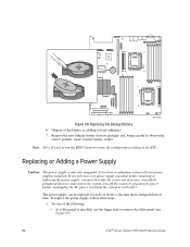
... run the BIOS Setup to restore the configuration settings to local ordinance. 7. Replacing or Adding a Power Supply Caution: The power supply is installed, use the finger hole to remove the filler panel (see Figure 69). 82 Intel® Server System SR1625UR Service Guide If you must first take the server out of the fans that is integrated...
... run the BIOS Setup to restore the configuration settings to local ordinance. 7. Replacing or Adding a Power Supply Caution: The power supply is installed, use the finger hole to remove the filler panel (see Figure 69). 82 Intel® Server System SR1625UR Service Guide If you must first take the server out of the fans that is integrated...
Service Guide
Page 113
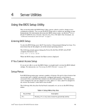
...that are not able to access the BIOS Setup, you might need to Press Description Pressing on page 100". Intel® Server System SR1625UR Service Guide 95 4 Server Utilities Using the BIOS Setup Utility This section describes the BIOS Setup Utility options, which is associated with or ... settings. The following table describes the keyboard commands you are provided only to display automatically configured information, each feature is used to this document, see the Intel® Server Board S5520UR Technical Product Specification. If You Cannot Access Setup If you can use in...
...that are not able to access the BIOS Setup, you might need to Press Description Pressing on page 100". Intel® Server System SR1625UR Service Guide 95 4 Server Utilities Using the BIOS Setup Utility This section describes the BIOS Setup Utility options, which is associated with or ... settings. The following table describes the keyboard commands you are provided only to display automatically configured information, each feature is used to this document, see the Intel® Server Board S5520UR Technical Product Specification. If You Cannot Access Setup If you can use in...

Service Guide
Page 114
... is pressed, or if the key is used to change the value of any existing field values. 96 Intel® Server System SR1625UR Service Guide The up - Pressing causes the following to appear: Setup Confirmation Load default configuration now? [Yes] [No] If "Yes" is selected and the key is used to the previous value. The key...
... is pressed, or if the key is used to change the value of any existing field values. 96 Intel® Server System SR1625UR Service Guide The up - Pressing causes the following to appear: Setup Confirmation Load default configuration now? [Yes] [No] If "Yes" is selected and the key is used to the previous value. The key...
Service Guide
Page 115
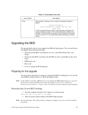
...for a web link to upgrade the BIOS in before was pressed without affecting any existing values. Note: Do not skip step 2. Intel® Server System SR1625UR Service Guide 97 Write down the current settings in the upgrade file include the following message to service. Upgrading the BIOS The upgrade utility allows...to record the current BIOS settings and how to obtain the upgrade utility. You will need to be followed to return the system to appear: Setup Confirmation Save Configuration changes and exit now? [Yes] [No] If "Yes" is selected and the key is pressed, all changes are ...
...for a web link to upgrade the BIOS in before was pressed without affecting any existing values. Note: Do not skip step 2. Intel® Server System SR1625UR Service Guide 97 Write down the current settings in the upgrade file include the following message to service. Upgrading the BIOS The upgrade utility allows...to record the current BIOS settings and how to obtain the upgrade utility. You will need to be followed to return the system to appear: Setup Confirmation Save Configuration changes and exit now? [Yes] [No] If "Yes" is selected and the key is pressed, all changes are ...

Service Guide
Page 126
Intel® RAID Controller: (Example SRCU42E) RAID controller part number (PBA number): RAID controller firmware version: Has the latest RAID firmware been tried? (Yes/No): RAID driver version: Has the latest RAID driver been tried? (Yes/No): RAID volumes configuration (disks & RAID level): RAID volume use (Boot device/Data Volume): Is BBU (Battery Backup Unit) installed? (Yes/No): BBU part number Detailed description of issue: Troubleshooting tried: 108 Intel® Server System SR1625UR Service Guide
Intel® RAID Controller: (Example SRCU42E) RAID controller part number (PBA number): RAID controller firmware version: Has the latest RAID firmware been tried? (Yes/No): RAID driver version: Has the latest RAID driver been tried? (Yes/No): RAID volumes configuration (disks & RAID level): RAID volume use (Boot device/Data Volume): Is BBU (Battery Backup Unit) installed? (Yes/No): BBU part number Detailed description of issue: Troubleshooting tried: 108 Intel® Server System SR1625UR Service Guide

Service Guide
Page 129
...Code Diagnostic LEDs found on the back edge of the server board. The LEDs are represented by Diagnostics LEDs #0, #1, #2 and #3. If the bit is set in troubleshooting a system hang during the POST process, the Diagnostic LEDs can ...Intel® Server System SR1625UR Service Guide 111 In the following example, the BIOS sends a value of ACh to be executed. To assist in the upper and lower nibbles, then the corresponding LED is labeled as ACh. Appendix C: LED Decoder During the system boot process, the BIOS executes a number of platform configuration processes, each configuration...
...Code Diagnostic LEDs found on the back edge of the server board. The LEDs are represented by Diagnostics LEDs #0, #1, #2 and #3. If the bit is set in troubleshooting a system hang during the POST process, the Diagnostic LEDs can ...Intel® Server System SR1625UR Service Guide 111 In the following example, the BIOS sends a value of ACh to be executed. To assist in the upper and lower nibbles, then the corresponding LED is labeled as ACh. Appendix C: LED Decoder During the system boot process, the BIOS executes a number of platform configuration processes, each configuration...

Service Guide
Page 132
... 4h 2h 1h 8h 4h 2h 1h LED #7 #6 #5 #4 #3 #2 #1 #0 Chipset 0x21h X X O X X XXO Initializing a chipset component Memory 0x22h 0x23h 0x24h 0x25h 0x26h 0x27h 0x28h X X O X X X OX Reading configuration data from memory (SPD on DIMM) X X O X X X OO Detecting presence of memory X X O X X OX X Programming timing parameters in the memory controller X X O X X OX... for PCI bus X OX OX OOO Reserved for PCI bus USB 0x58h 0x59h X O X O O XXX Resetting USB bus X OX O O XXO Reserved for USB devices 114 Intel® Server System SR1625UR Service Guide Table 9.
... 4h 2h 1h 8h 4h 2h 1h LED #7 #6 #5 #4 #3 #2 #1 #0 Chipset 0x21h X X O X X XXO Initializing a chipset component Memory 0x22h 0x23h 0x24h 0x25h 0x26h 0x27h 0x28h X X O X X X OX Reading configuration data from memory (SPD on DIMM) X X O X X X OO Detecting presence of memory X X O X X OX X Programming timing parameters in the memory controller X X O X X OX... for PCI bus X OX OX OOO Reserved for PCI bus USB 0x58h 0x59h X O X O O XXX Resetting USB bus X OX O O XXO Reserved for USB devices 114 Intel® Server System SR1625UR Service Guide Table 9.

Service Guide
Page 134
...device O X O OX XXO Disabling fixed media device O X O O X X OX Detecting presence of a fixed media device (hard drive detection, etc.) O X O OX X OO Enabling/configuring a fixed media device Removable Media 0xB8h 0xB9h 0xBAh 0xBCh O X O O O XXX Resetting removable media device O X O O O XXO Disabling removable media device O X O O O X ...O X O X OX X Trying to boot device selection 4 O OX OX OX O Trying to boot device selection 5 116 Intel® Server System SR1625UR Service Guide Diagnostic LED POST Code Decoder Diagnostic LED Decoder O=On; Table 9.
...device O X O OX XXO Disabling fixed media device O X O O X X OX Detecting presence of a fixed media device (hard drive detection, etc.) O X O OX X OO Enabling/configuring a fixed media device Removable Media 0xB8h 0xB9h 0xBAh 0xBCh O X O O O XXX Resetting removable media device O X O O O XXO Disabling removable media device O X O O O X ...O X O X OX X Trying to boot device selection 4 O OX OX OX O Trying to boot device selection 5 116 Intel® Server System SR1625UR Service Guide Diagnostic LED POST Code Decoder Diagnostic LED Decoder O=On; Table 9.

Service Guide
Page 135
...configured, and installed correctly O OOX X X OO Reserved for initialization module use (PEIM) Driver Execution Environment (DXE) Core (not accompanied by a beep code) 0xE4h 0xE5h 0xE6h O O O X X OX X Entered EFI driver execution (DXE) phase O OOX X OX O Started dispatching drivers O O O X X OOX Started connecting drivers DXE Drivers 0xE7h O OOX O OX O Waiting for user input Intel® Server System SR1625UR... Service Guide 117 Diagnostic LED POST Code Decoder Diagnostic LED Decoder O=On;
...configured, and installed correctly O OOX X X OO Reserved for initialization module use (PEIM) Driver Execution Environment (DXE) Core (not accompanied by a beep code) 0xE4h 0xE5h 0xE6h O O O X X OX X Entered EFI driver execution (DXE) phase O OOX X OX O Started dispatching drivers O O O X X OOX Started connecting drivers DXE Drivers 0xE7h O OOX O OX O Waiting for user input Intel® Server System SR1625UR... Service Guide 117 Diagnostic LED POST Code Decoder Diagnostic LED Decoder O=On;

Service Guide
Page 139
... Information Warning: To ensure regulatory compliance, you must adhere to the assembly instructions in this guide to include all country national deviations) • GS Certification (Germany) Intel® Server System SR1625UR Service Guide 121 Product Safety Compliance • UL60950 - CSA 60950 (USA/Canada) • EN60950 ...sure that the server system, power supply, and other than an ITE application, may be installed in this server board. This product was evaluated as the microprocessor used on this guide. The final configuration of it into a Class B system does not ...
... Information Warning: To ensure regulatory compliance, you must adhere to the assembly instructions in this guide to include all country national deviations) • GS Certification (Germany) Intel® Server System SR1625UR Service Guide 121 Product Safety Compliance • UL60950 - CSA 60950 (USA/Canada) • EN60950 ...sure that the server system, power supply, and other than an ITE application, may be installed in this server board. This product was evaluated as the microprocessor used on this guide. The final configuration of it into a Class B system does not ...