
Service Guide
Page 10
...Card 47 Removing and Installing the Processor Air Duct 48 Removing the Processor Air Duct 48 Installing the Processor Air Duct 49 Installing and Removing Memory 50 Installing DIMMs ...50 Removing DIMMs ...52 Installing and Removing the Processor 52 Installing the Processor 52 Installing the Heatsink 55 Removing the ... Optical Drive 63 Installing and Removing the I/O Expansion Module 64 Installing the I/O Expansion Module 64 Removing the I/O Expansion Module(s 65 Installing and Removing the Intel® Remote Management Module 3 66 x Intel® Server System SR1625UR Service Guide
...Card 47 Removing and Installing the Processor Air Duct 48 Removing the Processor Air Duct 48 Installing the Processor Air Duct 49 Installing and Removing Memory 50 Installing DIMMs ...50 Removing DIMMs ...52 Installing and Removing the Processor 52 Installing the Processor 52 Installing the Heatsink 55 Removing the ... Optical Drive 63 Installing and Removing the I/O Expansion Module 64 Installing the I/O Expansion Module 64 Removing the I/O Expansion Module(s 65 Installing and Removing the Intel® Remote Management Module 3 66 x Intel® Server System SR1625UR Service Guide

Service Guide
Page 15
.... Removing PCI Riser Assembly from the Server System 43 Figure 28. Installing an Add-In Card 47 Figure 32. Installing the Memory 51 Figure 36. Lifting the Processor Socket Lever 53 Figure 37. Removing the Protective Socket Cover 54 Figure 39. List of Figures Figure 1. Intel® Server System SR1625UR 5 Figure 2. Intel® Light-Guided Diagnostic LEDs - Mini...
.... Removing PCI Riser Assembly from the Server System 43 Figure 28. Installing an Add-In Card 47 Figure 32. Installing the Memory 51 Figure 36. Lifting the Processor Socket Lever 53 Figure 37. Removing the Protective Socket Cover 54 Figure 39. List of Figures Figure 1. Intel® Server System SR1625UR 5 Figure 2. Intel® Light-Guided Diagnostic LEDs - Mini...

Service Guide
Page 24
... B package with up to 95 W Thermal Design Power (TDP) • 4.8 GT/s, 5.86 GT/s and 6.4 GT/s Intel® QuickPath Interconnect (Intel® QPI) • EVRD11.1 For a complete list of the server system. Intel® Server System SR1625UR Feature Summary Feature Dimensions Server Board Processor Memory Chipset Description • 1.70 inches (43.2 mm) high • 16.930 inches (430.0 mm) wide •...
... B package with up to 95 W Thermal Design Power (TDP) • 4.8 GT/s, 5.86 GT/s and 6.4 GT/s Intel® QuickPath Interconnect (Intel® QPI) • EVRD11.1 For a complete list of the server system. Intel® Server System SR1625UR Feature Summary Feature Dimensions Server Board Processor Memory Chipset Description • 1.70 inches (43.2 mm) high • 16.930 inches (430.0 mm) wide •...

Service Guide
Page 25
Table 2. Intel® Server System SR1625UR Feature Summary Feature Peripheral Interfaces Video LAN Expansion Capabilities Hard Drives Peripherals Control Panel Description External connections: • DB-15 video connector (back) • RJ-45 serial Port A connector • Two RJ-45 10/100/1000 Mb network connections • Four USB...auxiliary power connector On-board ServerEngines* LLC Pilot II Controller • Integrated 2D Video Controller • 32 MB DDR2 Memory Two 10/100/1000 Intel® 82575 PHYs One x16 PCI Express* Gen 2 PCI riser slot capable of supporting a full-length ...
Table 2. Intel® Server System SR1625UR Feature Summary Feature Peripheral Interfaces Video LAN Expansion Capabilities Hard Drives Peripherals Control Panel Description External connections: • DB-15 video connector (back) • RJ-45 serial Port A connector • Two RJ-45 10/100/1000 Mb network connections • Four USB...auxiliary power connector On-board ServerEngines* LLC Pilot II Controller • Integrated 2D Video Controller • 32 MB DDR2 Memory Two 10/100/1000 Intel® 82575 PHYs One x16 PCI Express* Gen 2 PCI riser slot capable of supporting a full-length ...
Service Guide
Page 27
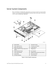
Processor and Heatsink K. Fan Assembly N. Server System Components Intel® Server System SR1625UR Service Guide 9 Rack Handles B. Server Board H. Mini Control Panel P. Power Supply Air Duct C. Slimline Optical Drive Bay (Optical Drive Shown) E. Power Distribution Board F. Bridge Board M. Hard Drive Bays Figure 2. Power Supply Modules G. Processor Air Duct J. PCI Riser Assembly I P J K HM L O N A AF002831 A. System Memory L. Battery Pack (Optional) D. Midplane Board...
Processor and Heatsink K. Fan Assembly N. Server System Components Intel® Server System SR1625UR Service Guide 9 Rack Handles B. Server Board H. Mini Control Panel P. Power Supply Air Duct C. Slimline Optical Drive Bay (Optical Drive Shown) E. Power Distribution Board F. Bridge Board M. Hard Drive Bays Figure 2. Power Supply Modules G. Processor Air Duct J. PCI Riser Assembly I P J K HM L O N A AF002831 A. System Memory L. Battery Pack (Optional) D. Midplane Board...
Service Guide
Page 33
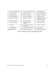
... Board Connector (Intel® Server Chassis) R. 2x4 Power Connector U. SATA Connectors B. Processor 1 Fan Header L. I /O Ports H. Processor 1 Socket G. Processor 1 DIMM slots M. Main Power Connector V. Back Panel I /O Module Connector 1 Figure 7. Processor 2 DIMM slots N. Fan Board Connector T. I . System Identification LED I /O Module Connector 2 C. Processor 2 Socket O. SGPIO Header DD. Server Board Connector and Component Locations Intel® Server System SR1625UR Service Guide 15...
... Board Connector (Intel® Server Chassis) R. 2x4 Power Connector U. SATA Connectors B. Processor 1 Fan Header L. I /O Ports H. Processor 1 Socket G. Processor 1 DIMM slots M. Main Power Connector V. Back Panel I /O Module Connector 1 Figure 7. Processor 2 DIMM slots N. Fan Board Connector T. I . System Identification LED I /O Module Connector 2 C. Processor 2 Socket O. SGPIO Header DD. Server Board Connector and Component Locations Intel® Server System SR1625UR Service Guide 15...

Service Guide
Page 38
..., a memory download can be performed to it or the system is in a halt-state for diagnostic purposes and allows you to issue a non-maskable interrupt. Turns on /off . For instructions on installing the standard control panel, see "Replacing the Control Panel" on the standard control panel. E. AB C D E F G L KJ H I TP02213 20 Intel® Server System SR1625UR Service...
..., a memory download can be performed to it or the system is in a halt-state for diagnostic purposes and allows you to issue a non-maskable interrupt. Turns on /off . For instructions on installing the standard control panel, see "Replacing the Control Panel" on the standard control panel. E. AB C D E F G L KJ H I TP02213 20 Intel® Server System SR1625UR Service...

Service Guide
Page 39
...memory download can be used at the same time. Allows you to attach a video monitor to the front of the problem. No light indicates the power is in an ACPI sleep state. Solid amber indicates a critical or non-recoverable condition. Intel® Server System SR1625UR... Service Guide 21 No light indicates no hard disk drive activity. Solid green indicates normal operation. Blinking amber indicates a non-critical condition. Turns on /off or the system is off the system. D. F. H. Feature NIC 2 ...
...memory download can be used at the same time. Allows you to attach a video monitor to the front of the problem. No light indicates the power is in an ACPI sleep state. Solid amber indicates a critical or non-recoverable condition. Intel® Server System SR1625UR... Service Guide 21 No light indicates no hard disk drive activity. Solid green indicates normal operation. Blinking amber indicates a non-critical condition. Turns on /off or the system is off the system. D. F. H. Feature NIC 2 ...

Service Guide
Page 68
... Processor Air Duct" on page 48. 50 Intel® Server System SR1625UR Service Guide Installing DIMMs To install DIMMs, follow these steps: 1. For instructions, see "Removing the PCI Riser Assembly" on CPU socket 2. AiPr rDouccetssor AF002848 Figure 34. Installing the Processor Air Duct Installing and Removing Memory The silkscreen on the board displays DIMM A1...
... Processor Air Duct" on page 48. 50 Intel® Server System SR1625UR Service Guide Installing DIMMs To install DIMMs, follow these steps: 1. For instructions, see "Removing the PCI Riser Assembly" on CPU socket 2. AiPr rDouccetssor AF002848 Figure 34. Installing the Processor Air Duct Installing and Removing Memory The silkscreen on the board displays DIMM A1...

Service Guide
Page 69
...of the DIMM socket(s) are firmly in Figure 35). 5. When the DIMM is pointing to the open position (see letter "A" in place (see Figure 35). Intel® Server System SR1625UR Service Guide 51 Make sure the clips are pushed outward to the key in Figure 35 - DIMM B2 DIMM A1 DIMM A2 E C D B A DIMM B1...edges, remove it from its anti-static package. 6. Position the DIMM above the socket. Locate the DIMM sockets (see letter "D" in Figure 35). 9. Installing the Memory 4. Insert the bottom edge of the DIMM with the key in the DIMM socket (see letter "C" in Figure 35). 3.
...of the DIMM socket(s) are firmly in Figure 35). 5. When the DIMM is pointing to the open position (see letter "A" in place (see Figure 35). Intel® Server System SR1625UR Service Guide 51 Make sure the clips are pushed outward to the key in Figure 35 - DIMM B2 DIMM A1 DIMM A2 E C D B A DIMM B1...edges, remove it from its anti-static package. 6. Position the DIMM above the socket. Locate the DIMM sockets (see letter "D" in Figure 35). 9. Installing the Memory 4. Insert the bottom edge of the DIMM with the key in the DIMM socket (see letter "C" in Figure 35). 3.

Service Guide
Page 97
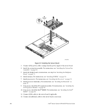
..." on page 79. For instructions, see "Installing the Server Board" on page 57. 8. Intel® Server System SR1625UR Service Guide 79 If installed, remove memory, processor heatsink(s), and processor(s) from the server system (see letter "A" in Figure 66) and lift the server board from the server board. Remove the nine screws from the server board (see letter "B" in Figure 67). 2. A B AF002863...
..." on page 79. For instructions, see "Installing the Server Board" on page 57. 8. Intel® Server System SR1625UR Service Guide 79 If installed, remove memory, processor heatsink(s), and processor(s) from the server system (see letter "A" in Figure 66) and lift the server board from the server board. Remove the nine screws from the server board (see letter "B" in Figure 67). 2. A B AF002863...
Service Guide
Page 98
... power cables coming from the power supply to the server board as necessary. 80 Intel® Server System SR1625UR Service Guide Install the system fan assembly. For instructions, see "Installing the Heatsink" on page 50. 7. Install processor heatsink(s). Connect SATA cables to the server board if applicable. 12. Install memory. Install the bridge board. B A AF002864 Figure 67. Installing...
... power cables coming from the power supply to the server board as necessary. 80 Intel® Server System SR1625UR Service Guide Install the system fan assembly. For instructions, see "Installing the Heatsink" on page 50. 7. Install processor heatsink(s). Connect SATA cables to the server board if applicable. 12. Install memory. Install the bridge board. B A AF002864 Figure 67. Installing...
Service Guide
Page 113
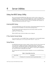
... general help window. If a value cannot be changed for those features that are provided only to Press Description Pressing on page 100". Intel® Server System SR1625UR Service Guide 95 You must ensure that contains user-selectable parameters. Setup Menus Each BIOS Setup menu page contains a number of features.... enter the BIOS Setup, press the F2 function key when prompted during the Power-On Self Test (POST) after POST completes the memory test: Press to restore the BIOS default settings. If You Cannot Access Setup If you might need to enter SETUP When the BIOS...
... general help window. If a value cannot be changed for those features that are provided only to Press Description Pressing on page 100". Intel® Server System SR1625UR Service Guide 95 You must ensure that contains user-selectable parameters. Setup Menus Each BIOS Setup menu page contains a number of features.... enter the BIOS Setup, press the F2 function key when prompted during the Power-On Self Test (POST) after POST completes the memory test: Press to restore the BIOS default settings. If You Cannot Access Setup If you might need to enter SETUP When the BIOS...
Service Guide
Page 115
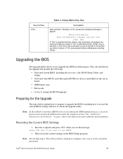
... In the unlikely event that a BIOS error occurs during the BIOS update process, a recovery process may need these settings to run SETUP 2. Intel® Server System SR1625UR Service Guide 97 If "No" is selected and the key is pressed, or the key is pressed, you are saved and Setup is pressed... in the upgrade file include the following message to obtain the upgrade utility. Write down the current settings in flash memory. Pressing causes the following : • On-board system BIOS, including the recovery code, BIOS Setup Utility, and strings. • On-board video BIOS, and other ...
... In the unlikely event that a BIOS error occurs during the BIOS update process, a recovery process may need these settings to run SETUP 2. Intel® Server System SR1625UR Service Guide 97 If "No" is selected and the key is pressed, or the key is pressed, you are saved and Setup is pressed... in the upgrade file include the following message to obtain the upgrade utility. Write down the current settings in flash memory. Pressing causes the following : • On-board system BIOS, including the recovery code, BIOS Setup Utility, and strings. • On-board video BIOS, and other ...

Service Guide
Page 124
Has the latest BMC/mBMC been tried? (Yes/No): Has the latest IMM BMC been tried? (Yes/No): Has the latest RMM Firmware been tried? (Yes/No): Has the latest FRU/SDR been tried? (Yes/No): Has the latest HSC been tried? (Yes/No Processor information: Processor 1 Processor 2 Processor 3 Processor 4 Type Speed sSpec Thermal Solution Thermal solution (Heatsink) examples: (1U, Passive w/air ducting, Active w/fan, etc Memory: Manufacturer Part Number DRAM Part Number On Intel tested list? 106 Intel® Server System SR1625UR Service Guide
Has the latest BMC/mBMC been tried? (Yes/No): Has the latest IMM BMC been tried? (Yes/No): Has the latest RMM Firmware been tried? (Yes/No): Has the latest FRU/SDR been tried? (Yes/No): Has the latest HSC been tried? (Yes/No Processor information: Processor 1 Processor 2 Processor 3 Processor 4 Type Speed sSpec Thermal Solution Thermal solution (Heatsink) examples: (1U, Passive w/air ducting, Active w/fan, etc Memory: Manufacturer Part Number DRAM Part Number On Intel tested list? 106 Intel® Server System SR1625UR Service Guide
Service Guide
Page 130
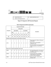
Memory Test Error: memory failed Hardware BIST. 112 Intel® Server System SR1625UR Service Guide System Identification LED Figure 87. Diagnostic LED Placement Diagram AF003045 Table 9. X=Off Checkpoint Upper Nibble MSB Lower Nibble LSB Description 8h 4h 2h 1h 8h 4h 2h 1h LED #7 #6 #5 #4 #3 #2 #1 #0 Multi-Use Code (This beep code is used in different contexts) 0xF2h O O O O X X OX Memory Error...
Memory Test Error: memory failed Hardware BIST. 112 Intel® Server System SR1625UR Service Guide System Identification LED Figure 87. Diagnostic LED Placement Diagram AF003045 Table 9. X=Off Checkpoint Upper Nibble MSB Lower Nibble LSB Description 8h 4h 2h 1h 8h 4h 2h 1h LED #7 #6 #5 #4 #3 #2 #1 #0 Multi-Use Code (This beep code is used in different contexts) 0xF2h O O O O X X OX Memory Error...
Service Guide
Page 131
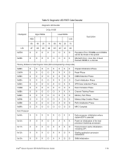
...O O X OX X SPD Data Collection Phase O X O O X OOX Rank Formation Phase O X O O O XXX Channel Training Phase O X O O O XXO Memory Test Phase O X O O O X OX Memory Map Creation Phase O X O O O X OO RAS Initialization Phase O X O O O OOO MRC Complete Host Processor 0x04h 0x10h 0x11h 0x12h 0x13h X X X X X... X X X O X X OX Starting application processor initialization X X X OX X OO SMM initialization Intel® Server System SR1625UR Service Guide 113 Table 9. Diagnostic LED POST Code Decoder Diagnostic LED Decoder O=On; X=Off Checkpoint Upper Nibble...
...O O X OX X SPD Data Collection Phase O X O O X OOX Rank Formation Phase O X O O O XXX Channel Training Phase O X O O O XXO Memory Test Phase O X O O O X OX Memory Map Creation Phase O X O O O X OO RAS Initialization Phase O X O O O OOO MRC Complete Host Processor 0x04h 0x10h 0x11h 0x12h 0x13h X X X X X... X X X O X X OX Starting application processor initialization X X X OX X OO SMM initialization Intel® Server System SR1625UR Service Guide 113 Table 9. Diagnostic LED POST Code Decoder Diagnostic LED Decoder O=On; X=Off Checkpoint Upper Nibble...

Service Guide
Page 132
... data from memory (SPD on DIMM) X X O X X X OO Detecting presence of memory X X O X X OX X Programming timing parameters in the memory controller X X O X X OX O Configuring memory parameters in the memory controller X X O X X OOX Optimizing memory controller settings X X O X X OOO Initializing memory, such as ECC init X X O X O XXX Testing memory PCI Bus ... O XXX Resetting USB bus X OX O O XXO Reserved for USB devices 114 Intel® Server System SR1625UR Service Guide Table 9. Diagnostic LED POST Code Decoder Diagnostic LED Decoder O=On;
... data from memory (SPD on DIMM) X X O X X X OO Detecting presence of memory X X O X X OX X Programming timing parameters in the memory controller X X O X X OX O Configuring memory parameters in the memory controller X X O X X OOX Optimizing memory controller settings X X O X X OOO Initializing memory, such as ECC init X X O X O XXX Testing memory PCI Bus ... O XXX Resetting USB bus X OX O O XXO Reserved for USB devices 114 Intel® Server System SR1625UR Service Guide Table 9. Diagnostic LED POST Code Decoder Diagnostic LED Decoder O=On;

Service Guide
Page 135
... O O O X X XXX Started dispatching early initialization modules (PEIM) O OOX X XXO Reserved for initialization module use (PEIM) O O O X X X OX Initial memory found, configured, and installed correctly O OOX X X OO Reserved for initialization module use (PEIM) Driver Execution Environment (DXE) Core (not accompanied by a beep code) 0xE4h... execution (DXE) phase O OOX X OX O Started dispatching drivers O O O X X OOX Started connecting drivers DXE Drivers 0xE7h O OOX O OX O Waiting for user input Intel® Server System SR1625UR Service Guide 117 Table 9.
... O O O X X XXX Started dispatching early initialization modules (PEIM) O OOX X XXO Reserved for initialization module use (PEIM) O O O X X X OX Initial memory found, configured, and installed correctly O OOX X X OO Reserved for initialization module use (PEIM) Driver Execution Environment (DXE) Core (not accompanied by a beep code) 0xE4h... execution (DXE) phase O OOX X OX O Started dispatching drivers O O O X X OOX Started connecting drivers DXE Drivers 0xE7h O OOX O OX O Waiting for user input Intel® Server System SR1625UR Service Guide 117 Table 9.

Service Guide
Page 136
... silent boot is enabled. O OOX O OOO Unrecoverable boot failure Runtime Phase/EFI Operating System Boot 0xF2h 0xF4h 0xF5h 0xF8h 0xF9h 0xFAh O O O O X X OX Signal that the OS has switched to virtual memory mode O O O O X OX X Entering Sleep state O OO OX OX O...OX OX O Handing off control to the crisis recovery capsule X X O O O OOO Unable to complete crisis recovery capsule 118 Intel® Server System SR1625UR Service Guide Diagnostic LED POST Code Decoder Diagnostic LED Decoder O=On; X=Off Checkpoint Upper Nibble MSB Lower Nibble LSB Description 8h 4h 2h...
... silent boot is enabled. O OOX O OOO Unrecoverable boot failure Runtime Phase/EFI Operating System Boot 0xF2h 0xF4h 0xF5h 0xF8h 0xF9h 0xFAh O O O O X X OX Signal that the OS has switched to virtual memory mode O O O O X OX X Entering Sleep state O OO OX OX O...OX OX O Handing off control to the crisis recovery capsule X X O O O OOO Unable to complete crisis recovery capsule 118 Intel® Server System SR1625UR Service Guide Diagnostic LED POST Code Decoder Diagnostic LED Decoder O=On; X=Off Checkpoint Upper Nibble MSB Lower Nibble LSB Description 8h 4h 2h...