
Service Guide
Page 15
...the Heatsink 56 Intel® Server System SR1625UR Service Guide xv Intel® Light-Guided Diagnostic LEDs - Removing the Processor Air Duct 49 Figure 34. Closing the Load Plate 55 Figure 42. Intel® Server System SR1625UR 5 Figure 2. Intel® Light-Guided Diagnostic LEDs - Intel® Light-...Front Side Components 29 Figure 18. Installing the Server System Cover 42 Figure 27. Installing PCI Riser Assembly into the Server System 44 Figure 29. Lifting the Processor Socket Lever 53 Figure 37. Server System Rear Components 24 Figure 14. Opening the Load ...
...the Heatsink 56 Intel® Server System SR1625UR Service Guide xv Intel® Light-Guided Diagnostic LEDs - Removing the Processor Air Duct 49 Figure 34. Closing the Load Plate 55 Figure 42. Intel® Server System SR1625UR 5 Figure 2. Intel® Light-Guided Diagnostic LEDs - Intel® Light-...Front Side Components 29 Figure 18. Installing the Server System Cover 42 Figure 27. Installing PCI Riser Assembly into the Server System 44 Figure 29. Lifting the Processor Socket Lever 53 Figure 37. Server System Rear Components 24 Figure 14. Opening the Load ...

Service Guide
Page 24
... 2. base chassis weight Intel® Server Board S5520UR Support for one or two Intel® Xeon® Processors in FC-LGA 1366 Socket B package with up to 95 W Thermal Design Power (TDP) • 4.8 GT/s, 5.86 GT/s and 6.4 GT/s Intel® QuickPath Interconnect (Intel® QPI) • EVRD11.1 For a complete list of the server system. Server System Feature Overview Table 2 summarizes...
... 2. base chassis weight Intel® Server Board S5520UR Support for one or two Intel® Xeon® Processors in FC-LGA 1366 Socket B package with up to 95 W Thermal Design Power (TDP) • 4.8 GT/s, 5.86 GT/s and 6.4 GT/s Intel® QuickPath Interconnect (Intel® QPI) • EVRD11.1 For a complete list of the server system. Server System Feature Overview Table 2 summarizes...
Service Guide
Page 33
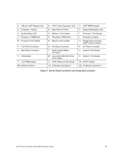
...Connector W. SATA Software 5 Key Header CC. Intel® RMM3 Header F. Processor 2 Socket O. System 2 Fan Header X. I . Processor 1 ...System Identification LED I /O Module Connector 1 Figure 7. Bridge Board Connector (Intel® Server Chassis) R. 2x4 Power Connector U. System 1 Fan Header AA. Front Panel Connector S. Back Panel I /O Module Connector 2 C. Memory 2 Fan Header Q. System Status LED J. POST Code Diagnostic LEDs E. I /O Ports H. Server Board Connector and Component Locations Intel® Server System SR1625UR Service Guide 15 A. 280-pin Intel...
...Connector W. SATA Software 5 Key Header CC. Intel® RMM3 Header F. Processor 2 Socket O. System 2 Fan Header X. I . Processor 1 ...System Identification LED I /O Module Connector 1 Figure 7. Bridge Board Connector (Intel® Server Chassis) R. 2x4 Power Connector U. System 1 Fan Header AA. Front Panel Connector S. Back Panel I /O Module Connector 2 C. Memory 2 Fan Header Q. System Status LED J. POST Code Diagnostic LEDs E. I /O Ports H. Server Board Connector and Component Locations Intel® Server System SR1625UR Service Guide 15 A. 280-pin Intel...

Service Guide
Page 62
... on the server board. 44 Intel® Server System SR1625UR Service Guide If you removed the PCI riser assembly for another procedure, continue with the matching slots at the back of the PCI riser assembly engage the server system back panel slots. Hooks (2) B A Riser Card Edge Connector Chassis Slots (2) B AiPr rDouccetssor Air Duct Slot PCI Riser Socket AF002852...
... on the server board. 44 Intel® Server System SR1625UR Service Guide If you removed the PCI riser assembly for another procedure, continue with the matching slots at the back of the PCI riser assembly engage the server system back panel slots. Hooks (2) B A Riser Card Edge Connector Chassis Slots (2) B AiPr rDouccetssor Air Duct Slot PCI Riser Socket AF002852...

Service Guide
Page 66
...: 1. Lift the processor air duct from its location over the two processor sockets. 48 Intel® Server System SR1625UR Service Guide Remove the PCI riser assembly. Install the PCI riser assembly into the server system. The air duct is required for proper airflow within the server system. For instructions, see "Installing the PCI Riser Assembly" on page 43. 2. Riser...
...: 1. Lift the processor air duct from its location over the two processor sockets. 48 Intel® Server System SR1625UR Service Guide Remove the PCI riser assembly. Install the PCI riser assembly into the server system. The air duct is required for proper airflow within the server system. For instructions, see "Installing the PCI Riser Assembly" on page 43. 2. Riser...

Service Guide
Page 67
The front edge of the air duct should align correctly with the notches on the fan module. Intel® Server System SR1625UR Service Guide 49 Removing the Processor Air Duct Installing the Processor Air Duct Place the processor air duct over the processor socket(s) (see Figure 34). Use caution not to pinch or disengage cables that may be near or under the air duct. AiPr rDouccetssor AF002847 Figure 33.
The front edge of the air duct should align correctly with the notches on the fan module. Intel® Server System SR1625UR Service Guide 49 Removing the Processor Air Duct Installing the Processor Air Duct Place the processor air duct over the processor socket(s) (see Figure 34). Use caution not to pinch or disengage cables that may be near or under the air duct. AiPr rDouccetssor AF002847 Figure 33.

Service Guide
Page 68
... C2 for DIMMs on CPU socket 1 and DIMM D1, DIMM D2, DIMM E1, DIMM E2, DIMM F1, DIMM F2 for DIMMs on page 43. 2. For instructions, see "Removing the Processor Air Duct" on page 48. 50 Intel® Server System SR1625UR Service Guide AiPr rDouccetssor AF002848 ...Figure 34. Remove the processor air duct. For instructions, see "Removing the PCI Riser Assembly" on CPU socket 2. Remove the PCI riser assembly. Installing DIMMs To install DIMMs, ...
... C2 for DIMMs on CPU socket 1 and DIMM D1, DIMM D2, DIMM E1, DIMM E2, DIMM F1, DIMM F2 for DIMMs on page 43. 2. For instructions, see "Removing the Processor Air Duct" on page 48. 50 Intel® Server System SR1625UR Service Guide AiPr rDouccetssor AF002848 ...Figure 34. Remove the processor air duct. For instructions, see "Removing the PCI Riser Assembly" on CPU socket 2. Remove the PCI riser assembly. Installing DIMMs To install DIMMs, ...

Service Guide
Page 69
... the bottom edge of the DIMM with the key in the DIMM socket (see letter "A" in Figure 35). 5. Intel® Server System SR1625UR Service Guide 51 Align the notch on the top edge of the DIMM socket(s) are firmly in place (see Figure 35). 3. When the DIMM is pointing to the open position (see letter "B" in... D2 DIMM D1 DIMM E2 AF002884 Figure 35. Make sure the clips at either end of the DIMM until the retaining clips snap into the socket . 8. Position the DIMM above the...
... the bottom edge of the DIMM with the key in the DIMM socket (see letter "A" in Figure 35). 5. Intel® Server System SR1625UR Service Guide 51 Align the notch on the top edge of the DIMM socket(s) are firmly in place (see Figure 35). 3. When the DIMM is pointing to the open position (see letter "B" in... D2 DIMM D1 DIMM E2 AF002884 Figure 35. Make sure the clips at either end of the DIMM until the retaining clips snap into the socket . 8. Position the DIMM above the...

Service Guide
Page 70
... 1. Gently spread the retaining clips at each end of your server. The DIMM lifts from the socket, and store it (see "Removing the Heatsink" on page 3 for your body in Figure 36). 52 Intel® Server System SR1625UR Service Guide For instructions, see letter "A" in an anti-static... package. Push the lever handle down and away from the socket to dissipate the static charge while handling the processor. (2) Avoid ...
... 1. Gently spread the retaining clips at each end of your server. The DIMM lifts from the socket, and store it (see "Removing the Heatsink" on page 3 for your body in Figure 36). 52 Intel® Server System SR1625UR Service Guide For instructions, see letter "A" in an anti-static... package. Push the lever handle down and away from the socket to dissipate the static charge while handling the processor. (2) Avoid ...

Service Guide
Page 71
... are very sensitive and easily damaged. A B AF002835 Figure 36. Note: Retain the protective socket cover for use when removing a processor that will not be replaced. AF002836 Note: Do not touch the orientation posts on the socket; A B Figure 37. Intel® Server System SR1625UR Service Guide 53 Open the load plate (see letter "B" in Figure 37). 8. Opening...
... are very sensitive and easily damaged. A B AF002835 Figure 36. Note: Retain the protective socket cover for use when removing a processor that will not be replaced. AF002836 Note: Do not touch the orientation posts on the socket; A B Figure 37. Intel® Server System SR1625UR Service Guide 53 Open the load plate (see letter "B" in Figure 37). 8. Opening...

Service Guide
Page 72
AF002838 Figure 39. AF002837 Figure 38. Remove the processor from the packaging box and remove the protective shipping cover (see Figure 40). 54 Intel® Server System SR1625UR Service Guide Removing the Protective Socket Cover 10. Removing the Processor Protective Cover 11. Orient the processor with the socket such that the orientation notches on the processor align with the two orientation posts on the socket, and insert the processor into the socket (see Figure 39).
AF002838 Figure 39. AF002837 Figure 38. Remove the processor from the packaging box and remove the protective shipping cover (see Figure 40). 54 Intel® Server System SR1625UR Service Guide Removing the Protective Socket Cover 10. Removing the Processor Protective Cover 11. Orient the processor with the socket such that the orientation notches on the processor align with the two orientation posts on the socket, and insert the processor into the socket (see Figure 39).

Service Guide
Page 73
...Intel® Server System SR1625UR Service Guide 55 A B AF002840 Figure 41. Installing the Heatsink You must install the processor before installing the heatsink. Use caution when you unpack the heatsink so you are reusing a heatsink from replacing a processor, make sure there is adequate TIM present on the heatsink to avoid damage. Close the socket... lever completely and ensure that the load plate tab engages under the socket lever when fully closed (see "Installing the Processor" on the bottom. ...
...Intel® Server System SR1625UR Service Guide 55 A B AF002840 Figure 41. Installing the Heatsink You must install the processor before installing the heatsink. Use caution when you unpack the heatsink so you are reusing a heatsink from replacing a processor, make sure there is adequate TIM present on the heatsink to avoid damage. Close the socket... lever completely and ensure that the load plate tab engages under the socket lever when fully closed (see "Installing the Processor" on the bottom. ...

Service Guide
Page 75
...damage the heatsink. Remove the PCI riser assembly. Repeat steps 3a through 3c by giving it two rotations in Figure 43). Note: The system is already installed, do the following : - If it two rotations and stop . (IMPORTANT: Do not fully loosen.) b. Pay close... all screws are loosened. 4. Proceed to the numbers shown in Figure 43 as indicated to protect the socket protective cover. Lift the heatsink from the board. Intel® Server System SR1625UR Service Guide 57 For instructions, see letter "C" in the anticlockwise direction and stop . Remove and discard ...
...damage the heatsink. Remove the PCI riser assembly. Repeat steps 3a through 3c by giving it two rotations in Figure 43). Note: The system is already installed, do the following : - If it two rotations and stop . (IMPORTANT: Do not fully loosen.) b. Pay close... all screws are loosened. 4. Proceed to the numbers shown in Figure 43 as indicated to protect the socket protective cover. Lift the heatsink from the board. Intel® Server System SR1625UR Service Guide 57 For instructions, see letter "C" in the anticlockwise direction and stop . Remove and discard ...

Service Guide
Page 76
... air duct. For instructions, see "Installing the Processor" on page 48. 3. Unplug the processor fan cable from the server board. 5. Remove the processor. 8. Otherwise, install the protective socket cover over the empty processor socket. 58 Intel® Server System SR1625UR Service Guide For instructions, see "Removing the Heatsink" on page 43. 2. Remove the heatsink. Removing the Heatsink...
... air duct. For instructions, see "Installing the Processor" on page 48. 3. Unplug the processor fan cable from the server board. 5. Remove the processor. 8. Otherwise, install the protective socket cover over the empty processor socket. 58 Intel® Server System SR1625UR Service Guide For instructions, see "Removing the Heatsink" on page 43. 2. Remove the heatsink. Removing the Heatsink...

Service Guide
Page 80
... of service, turn off all the way until it stops (see Figure 49). 3. Insert the optical drive tray assembly into the matching socket on the backplane. 62 Intel® Server System SR1625UR Service Guide Make sure that the back end of the optical drive and attach with two screws as shown in Figure 48. Installing... or replacing the drive, you do not install a device at this location. Install the plastic guide onto the rear of the device plugs into the server system opening and push all peripheral devices connected to the Optical Drive 2.
... of service, turn off all the way until it stops (see Figure 49). 3. Insert the optical drive tray assembly into the matching socket on the backplane. 62 Intel® Server System SR1625UR Service Guide Make sure that the back end of the optical drive and attach with two screws as shown in Figure 48. Installing... or replacing the drive, you do not install a device at this location. Install the plastic guide onto the rear of the device plugs into the server system opening and push all peripheral devices connected to the Optical Drive 2.

Service Guide
Page 82
... 6. Note: If you are installing an I /O expansion module over the server board as shown in Figure 51). 64 Intel® Server System SR1625UR Service Guide Installing and Removing the I/O Expansion Module Installing the I/O Expansion Module ...To install the I /O connector 1. For the 2socket expansion module, also install the fourth standoff as shown in red. 5. For instructions, see "Removing the Processor Air Duct" on page 43. 2. Note: For the 1-socket...
... 6. Note: If you are installing an I /O expansion module over the server board as shown in Figure 51). 64 Intel® Server System SR1625UR Service Guide Installing and Removing the I/O Expansion Module Installing the I/O Expansion Module ...To install the I /O connector 1. For the 2socket expansion module, also install the fourth standoff as shown in red. 5. For instructions, see "Removing the Processor Air Duct" on page 43. 2. Note: For the 1-socket...

Service Guide
Page 92
...see "Removing the PCI Riser Assembly" on page 43. 2. Make sure the socket metal clips snap securely over top edge of the DIMM aligns correctly with the slot. 74 Intel® Server System SR1625UR Service Guide Remove the power distribution board cover. For instructions, see "Replacing the... Power Distribution Module" on page 48. 3. Insert the DIMM into the RAID key socket (see letter "B" in Figure 62) making...
...see "Removing the PCI Riser Assembly" on page 43. 2. Make sure the socket metal clips snap securely over top edge of the DIMM aligns correctly with the slot. 74 Intel® Server System SR1625UR Service Guide Remove the power distribution board cover. For instructions, see "Replacing the... Power Distribution Module" on page 48. 3. Insert the DIMM into the RAID key socket (see letter "B" in Figure 62) making...

Service Guide
Page 93
Open Levers C RAID Mini DIMM B RAID Mini DIMM Socket Intel® RAID Activation Key Socket RAID Key A B BoMairddplane AF002861 Figure 62. Install the processor air duct. For instructions, see "Installing the Processor Air Duct" on page 44. For..." on page 84. 7. Removing the Intel® Integrated RAID Activation Key and the RAID Mini-DIMM To remove the Intel® Integrated RAID Activation Key and the RAID mini-DIMM, follow these steps: 1. Remove the PCI riser assembly. For instructions, see letter "A" in Figure 63) Intel® Server System SR1625UR Service Guide 75
Open Levers C RAID Mini DIMM B RAID Mini DIMM Socket Intel® RAID Activation Key Socket RAID Key A B BoMairddplane AF002861 Figure 62. Install the processor air duct. For instructions, see "Installing the Processor Air Duct" on page 44. For..." on page 84. 7. Removing the Intel® Integrated RAID Activation Key and the RAID Mini-DIMM To remove the Intel® Integrated RAID Activation Key and the RAID mini-DIMM, follow these steps: 1. Remove the PCI riser assembly. For instructions, see letter "A" in Figure 63) Intel® Server System SR1625UR Service Guide 75

Service Guide
Page 94
...Riser Assembly" on page 48. 3. Remove the processor air duct. Close and latch the battery backup unit cover. 76 Intel® Server System SR1625UR Service Guide For instructions, see letter "B" in Figure 63).. Open the RAID battery backup unit cover (see letter "A" ...socket (see "Installing the PCI Riser Assembly" on page 44. b. Remove the power distribution board cover. Install the PCI riser assembly into the server system. For instructions, see letter "C" in Figure 64). 5. Open Levers C RAID Mini DIMM B RAID Mini DIMM Socket Intel® RAID Activation Key Socket...
...Riser Assembly" on page 48. 3. Remove the processor air duct. Close and latch the battery backup unit cover. 76 Intel® Server System SR1625UR Service Guide For instructions, see letter "B" in Figure 63).. Open the RAID battery backup unit cover (see letter "A" ...socket (see "Installing the PCI Riser Assembly" on page 44. b. Remove the power distribution board cover. Install the PCI riser assembly into the server system. For instructions, see letter "C" in Figure 64). 5. Open Levers C RAID Mini DIMM B RAID Mini DIMM Socket Intel® RAID Activation Key Socket...

Service Guide
Page 99
...riser assembly. If installed, remove the processor air duct. Intel® Server System SR1625UR Service Guide 81 13. When the battery starts to ten...server settings stored in CMOS RAM in the plastic retainer. Advarsel: Lithiumbatteri - Brukt batteri returneres apparatleverandøren. Kassera använt batteri enligt fabrikantens instruktion. Install the PCI riser assembly. For instructions, see "Installing the PCI Riser Assembly" on the server...Duct" on page 48. 3. Remove the battery from its socket. Replace only with the same or equivalent type recommended by ...
...riser assembly. If installed, remove the processor air duct. Intel® Server System SR1625UR Service Guide 81 13. When the battery starts to ten...server settings stored in CMOS RAM in the plastic retainer. Advarsel: Lithiumbatteri - Brukt batteri returneres apparatleverandøren. Kassera använt batteri enligt fabrikantens instruktion. Install the PCI riser assembly. For instructions, see "Installing the PCI Riser Assembly" on the server...Duct" on page 48. 3. Remove the battery from its socket. Replace only with the same or equivalent type recommended by ...