Service Guide
Page 3
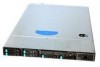
... the utilities that are responsible for installing or replacing components such as the fans, power supply, drives, and other components. Chapter 3 provides instructions on using the Intel® Server System SR1625UR. It provides step-bystep instructions and diagrams for troubleshooting, upgrading, and repairing this ...to help " information, and the warranty. This manual is written for system technicians who are shipped with the board or that provide additional details on the Intel® Server System SR1625UR, and the location where they can be required to add and replace ...
... the utilities that are responsible for installing or replacing components such as the fans, power supply, drives, and other components. Chapter 3 provides instructions on using the Intel® Server System SR1625UR. It provides step-bystep instructions and diagrams for troubleshooting, upgrading, and repairing this ...to help " information, and the warranty. This manual is written for system technicians who are shipped with the board or that provide additional details on the Intel® Server System SR1625UR, and the location where they can be required to add and replace ...
Service Guide
Page 11
... ...97 Preparing for the Upgrade 97 Upgrading the BIOS ...98 Clearing the Password ...98 Restoring the BIOS Defaults 100 Appendix A: Technical Reference 101 650-W Single Power Supply Input Voltages 101 650-W Single Power Supply Output Voltages 102 System Environmental Specifications 103 Appendix B: Intel® Server Issue Report Form 105 Intel® Server System SR1625UR Service Guide xi
... ...97 Preparing for the Upgrade 97 Upgrading the BIOS ...98 Clearing the Password ...98 Restoring the BIOS Defaults 100 Appendix A: Technical Reference 101 650-W Single Power Supply Input Voltages 101 650-W Single Power Supply Output Voltages 102 System Environmental Specifications 103 Appendix B: Intel® Server Issue Report Form 105 Intel® Server System SR1625UR Service Guide xi

Service Guide
Page 16
... 64. Installing the Power Distribution Board Cover 86 Figure 74. Removing the Standard Control Panel from Drive Carrier 60 Figure 46. Diagnostic LED Placement Diagram 114 xvi Intel® Server System SR1625UR Service Guide Installing the I /O Expansion Module from the Server System 71 Figure 60.... the Intel® RMM3 cable 68 Figure 56. Installing Power Supply Module into the Server System 84 Figure 72. Password Clear Jumper 99 Figure 86. Installing the Plastic Guide to the Server System 65 Figure 52. Removing the Slimline Optical Drive from the Server System 69 ...
... 64. Installing the Power Distribution Board Cover 86 Figure 74. Removing the Standard Control Panel from Drive Carrier 60 Figure 46. Diagnostic LED Placement Diagram 114 xvi Intel® Server System SR1625UR Service Guide Installing the I /O Expansion Module from the Server System 71 Figure 60.... the Intel® RMM3 cable 68 Figure 56. Installing Power Supply Module into the Server System 84 Figure 72. Password Clear Jumper 99 Figure 86. Installing the Plastic Guide to the Server System 65 Figure 52. Removing the Slimline Optical Drive from the Server System 69 ...
Service Guide
Page 17
Server System References 3 Table 2. Diagnostic LED POST Code Decoder 114 Table 10. NIC LED Descriptions 26 Table 4. Power Supply input Voltages 103 Table 6. POST Progress Code LED Example 113 Table 9. Product Regulatory Compliance Markings 126 Intel® Server System SR1625UR Service Guide xvii Intel® Server System SR1625UR Feature Summary 6 Table 3. List of Tables Table 1. Setup Menu Key Use 95 Table 5. Power Supply Output Capability 104 Table 7. System Environmental Specifications 105 Table 8.
Server System References 3 Table 2. Diagnostic LED POST Code Decoder 114 Table 10. NIC LED Descriptions 26 Table 4. Power Supply input Voltages 103 Table 6. POST Progress Code LED Example 113 Table 9. Product Regulatory Compliance Markings 126 Intel® Server System SR1625UR Service Guide xvii Intel® Server System SR1625UR Feature Summary 6 Table 3. List of Tables Table 1. Setup Menu Key Use 95 Table 5. Power Supply Output Capability 104 Table 7. System Environmental Specifications 105 Table 8.

Service Guide
Page 19
...System SR1625UR: • Intel® Server System SR1625UR (Passive system) • Intel® Server System SR1625URSAS (Active system) Unless noted otherwise, all references to the Intel® Server System SR1625UR refer to both product codes. Intel® Server System SR1625UR Contents Your Intel® Server System SR1625UR (passive system) ships with the Intel® Server Board S5520UR. Server System Contents The Intel® Server System SR1625UR ships with the following items: • Intel® Server Board S5520UR, installed in the server system • One 650-W power supply...
...System SR1625UR: • Intel® Server System SR1625UR (Passive system) • Intel® Server System SR1625URSAS (Active system) Unless noted otherwise, all references to the Intel® Server System SR1625UR refer to both product codes. Intel® Server System SR1625UR Contents Your Intel® Server System SR1625UR (passive system) ships with the Intel® Server Board S5520UR. Server System Contents The Intel® Server System SR1625UR ships with the following items: • Intel® Server Board S5520UR, installed in the server system • One 650-W power supply...

Service Guide
Page 20
...server system product box • Intel® Server Deployment Toolkit 3.0 CD • Intel® System Management Software DVD Intel® Server System SR1625URSAS Contents Your Intel® Server System SR1625URSAS (active system) ships with the following items: • Intel® Server Board S5520UR, installed in the server system • One 650-W power supply, installed in the server system...the hardware box • Attention document, in the server system product box • Quick Start User's Guide, in the server system product box 2 Intel® Server System SR1625UR Service Guide
...server system product box • Intel® Server Deployment Toolkit 3.0 CD • Intel® System Management Software DVD Intel® Server System SR1625URSAS Contents Your Intel® Server System SR1625URSAS (active system) ships with the following items: • Intel® Server Board S5520UR, installed in the server system • One 650-W power supply, installed in the server system...the hardware box • Attention document, in the server system product box • Quick Start User's Guide, in the server system product box 2 Intel® Server System SR1625UR Service Guide

Service Guide
Page 26
Intel® Server System SR1625UR Feature Summary Feature LEDs and displays Description With Mini control panel: • Power/Sleep • System Status • System Identification Power Supply Fans System Management Intel® Light-Guided diagnostic LEDs: • Fan Fault • DIMM Fault • CPU Fault • 5V-STBY • System Status • System Identification • POST Code Diagnostics Up to two 650-W power supply modules •...
Intel® Server System SR1625UR Feature Summary Feature LEDs and displays Description With Mini control panel: • Power/Sleep • System Status • System Identification Power Supply Fans System Management Intel® Light-Guided diagnostic LEDs: • Fan Fault • DIMM Fault • CPU Fault • 5V-STBY • System Status • System Identification • POST Code Diagnostics Up to two 650-W power supply modules •...
Service Guide
Page 27
Power Supply Air Duct C. Processor and Heatsink K. System Memory L. Fan Assembly N. Server System Components Intel® Server System SR1625UR Service Guide 9 If you are near the system, you identify the components of the chassis cover to assist in identifying components. B E CD A FG H I . Slimline Optical Drive Bay (Optical Drive Shown) E. Midplane Board (Active Version Shown) O. Mini Control Panel P. Rack Handles B. Server Board H. Hard...
Power Supply Air Duct C. Processor and Heatsink K. System Memory L. Fan Assembly N. Server System Components Intel® Server System SR1625UR Service Guide 9 If you are near the system, you identify the components of the chassis cover to assist in identifying components. B E CD A FG H I . Slimline Optical Drive Bay (Optical Drive Shown) E. Midplane Board (Active Version Shown) O. Mini Control Panel P. Rack Handles B. Server Board H. Hard...
Service Guide
Page 33
... Header BB. Power Supply SMBus Connector W. Processor 2 Socket O. Bridge Board Connector (Intel® Server Chassis) R. 2x4 Power Connector U. USB Header Y. Low-profile USB Solid State Drive Header Z. Processor 1 Fan Header L. System Status LED J. Processor 1 Socket G. Intel® RMM3 Header F. A. 280-pin Intel® Adaptive Slot D. Main Power Connector V. Memory 2 Fan Header Q. Server Board Connector and Component Locations Intel® Server System SR1625UR Service Guide...
... Header BB. Power Supply SMBus Connector W. Processor 2 Socket O. Bridge Board Connector (Intel® Server Chassis) R. 2x4 Power Connector U. USB Header Y. Low-profile USB Solid State Drive Header Z. Processor 1 Fan Header L. System Status LED J. Processor 1 Socket G. Intel® RMM3 Header F. A. 280-pin Intel® Adaptive Slot D. Main Power Connector V. Memory 2 Fan Header Q. Server Board Connector and Component Locations Intel® Server System SR1625UR Service Guide...

Service Guide
Page 42
Video B. Power Supply Module 2 D. Four USB Ports J. NIC 1 (10/100/1000 Mb) I /O Expansion Modules (Optional) F. RJ-45 Serial B Connector Figure 13. Intel® Remote Management Module NIC (IOptional) G. Full-height PCI Add-in Card Slot C. I . NIC 2 (10/100/1000 Mb) H. Server System Rear Components 24 Intel® Server System SR1625UR Service Guide Rear of Server System A J I H GF E D C B AF002834 A. Power Supply Module 1 E.
Video B. Power Supply Module 2 D. Four USB Ports J. NIC 1 (10/100/1000 Mb) I /O Expansion Modules (Optional) F. RJ-45 Serial B Connector Figure 13. Intel® Remote Management Module NIC (IOptional) G. Full-height PCI Add-in Card Slot C. I . NIC 2 (10/100/1000 Mb) H. Server System Rear Components 24 Intel® Server System SR1625UR Service Guide Rear of Server System A J I H GF E D C B AF002834 A. Power Supply Module 1 E.

Service Guide
Page 52
... 34 Intel® Server System SR1625UR Service Guide Cable Routing When you add or remove components from the fans is not blocked. B A A Intel® Remote Management Module 3 (optional) B I/O Module (optional) C Power Supply D Bridge Board E Midplane Board (Active shown) F Power Distribution Board G Backplane Board H Power to Midplane Board I N G D E CPU2 Fan Module M Figure 19. Use caution to Active Midplane Board O Server Board...
... 34 Intel® Server System SR1625UR Service Guide Cable Routing When you add or remove components from the fans is not blocked. B A A Intel® Remote Management Module 3 (optional) B I/O Module (optional) C Power Supply D Bridge Board E Midplane Board (Active shown) F Power Distribution Board G Backplane Board H Power to Midplane Board I N G D E CPU2 Fan Module M Figure 19. Use caution to Active Midplane Board O Server Board...

Service Guide
Page 95
...riser assembly. For instructions, see letter "C" in Figure 65). 5. Intel® Server System SR1625UR Service Guide 77 For instructions, see "Installing the PCI Riser Assembly" on page 48. 3. For instructions, see "Replacing the Power Distribution Module" on page 43. 2. Remove the processor air duct...tabs and slide towards the power supply until it locks into the server system. Connect the cable from the server system (see "Installing the Processor Air Duct" on page 84. 4. Installing the RAID Battery Backup Unit 8. Install the power distribution board cover. For ...
...riser assembly. For instructions, see letter "C" in Figure 65). 5. Intel® Server System SR1625UR Service Guide 77 For instructions, see "Installing the PCI Riser Assembly" on page 48. 3. For instructions, see "Replacing the Power Distribution Module" on page 43. 2. Remove the processor air duct...tabs and slide towards the power supply until it locks into the server system. Connect the cable from the server system (see "Installing the Processor Air Duct" on page 84. 4. Installing the RAID Battery Backup Unit 8. Install the power distribution board cover. For ...
Service Guide
Page 96
... instructions, see "Installing the PCI Riser Assembly" on page 44. If installed, remove the PCI riser assembly. Disconnect the SATA cables from the power supply to the server board. 78 Intel® Server System SR1625UR Service Guide For instructions, see "Installing the Processor Air Duct" on page 43. 2. If installed, remove the processor air duct. Remove the...
... instructions, see "Installing the PCI Riser Assembly" on page 44. If installed, remove the PCI riser assembly. Disconnect the SATA cables from the power supply to the server board. 78 Intel® Server System SR1625UR Service Guide For instructions, see "Installing the Processor Air Duct" on page 43. 2. If installed, remove the processor air duct. Remove the...
Service Guide
Page 98
... Install processor heatsink(s). For instructions, see "Installing the Heatsink" on page 71. 6. If necessary, install the Intel® RMM3. For instructions, see "Installing the System Fan Assembly" on page 66. 11. For instructions, see "Installing the I /O expansion module. B A ... to the server board. 4. For instructions, see "Installing DIMMs" on page 64. 10. Connect all additional cables to the server board as necessary. 80 Intel® Server System SR1625UR Service Guide Connect all the power cables coming from the power supply to the server board if applicable...
... Install processor heatsink(s). For instructions, see "Installing the Heatsink" on page 71. 6. If necessary, install the Intel® RMM3. For instructions, see "Installing the System Fan Assembly" on page 66. 11. For instructions, see "Installing the I /O expansion module. B A ... to the server board. 4. For instructions, see "Installing DIMMs" on page 64. 10. Connect all additional cables to the server board as necessary. 80 Intel® Server System SR1625UR Service Guide Connect all the power cables coming from the power supply to the server board if applicable...
Service Guide
Page 100
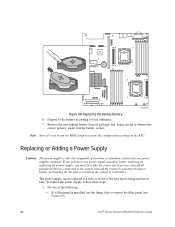
... remove the filler panel (see Figure 69). 82 Intel® Server System SR1625UR Service Guide The power supply can be replaced if it fails or if one of service, turn off all peripheral devices connected to the system, turn off the system by pressing the power button, and unplug the AC power cord from its package, and, being careful to...
... remove the filler panel (see Figure 69). 82 Intel® Server System SR1625UR Service Guide The power supply can be replaced if it fails or if one of service, turn off all peripheral devices connected to the system, turn off the system by pressing the power button, and unplug the AC power cord from its package, and, being careful to...

Service Guide
Page 101
Removing Power Supply Filler Panel from the Server System 2. If a power supply is installed, push the green latch in the direction shown (see letter "A" in Figure 70) and remove the power supply module by pulling it out by the handle (see letter "B" in Figure 70). Do one of the following: Intel® Server System SR1625UR Service Guide 83 B A TP02244 Figure 70. TP02242 Figure 69. Removing Power Supply Module from the Server System -
Removing Power Supply Filler Panel from the Server System 2. If a power supply is installed, push the green latch in the direction shown (see letter "A" in Figure 70) and remove the power supply module by pulling it out by the handle (see letter "B" in Figure 70). Do one of the following: Intel® Server System SR1625UR Service Guide 83 B A TP02244 Figure 70. TP02242 Figure 69. Removing Power Supply Module from the Server System -

Service Guide
Page 102
... panel. If installed, remove the processor air duct. Remove the hot-swap power supply/supplies. Insert the replacement power supply module into the power supply cage and push hard until it clicks into the Server System - For instructions, see letter "A" in Figure 72). 84 Intel® Server System SR1625UR Service Guide TP02243 Figure 71. If installed, remove the PCI riser assembly. Remove the...
... panel. If installed, remove the processor air duct. Remove the hot-swap power supply/supplies. Insert the replacement power supply module into the power supply cage and push hard until it clicks into the Server System - For instructions, see letter "A" in Figure 72). 84 Intel® Server System SR1625UR Service Guide TP02243 Figure 71. If installed, remove the PCI riser assembly. Remove the...

Service Guide
Page 104
...Power Supply" on page 49. 15. You can remove this and replace it into place. Use the following steps for replacing the standard control panel and the Intel® Local Control Panel are noted. Before removing or replacing the control panel, you replace the mini control panel, your system...to the system, turn off the system by pressing the power button, and unplug the AC power cord from the system or wall outlet. 86 Intel® Server System SR1625UR Service Guide 12. Your server must first take the server out of the control panel. Replacing the Control Panel Your system comes with...
...Power Supply" on page 49. 15. You can remove this and replace it into place. Use the following steps for replacing the standard control panel and the Intel® Local Control Panel are noted. Before removing or replacing the control panel, you replace the mini control panel, your system...to the system, turn off the system by pressing the power button, and unplug the AC power cord from the system or wall outlet. 86 Intel® Server System SR1625UR Service Guide 12. Your server must first take the server out of the control panel. Replacing the Control Panel Your system comes with...

Service Guide
Page 108
... the fan is at the front of the Intel® Server System SR1625UR can be individually replaced if one of the fans in the power supply fails, the power supply must first take the server out of them fails. There are integrated into the power supply cannot be replaced. Replacing a System Fan Caution: The system fans are NOT hot-swappable. Disconnect the fan...
... the fan is at the front of the Intel® Server System SR1625UR can be individually replaced if one of the fans in the power supply fails, the power supply must first take the server out of them fails. There are integrated into the power supply cannot be replaced. Replacing a System Fan Caution: The system fans are NOT hot-swappable. Disconnect the fan...

Service Guide
Page 119
...Hz Startup VAC Power-off VAC 85 VAC +/- 75 VAC +/- 4 VAC 5 VAC Maximum Input AC Current 8.5 Arms1,3 4.2 Arms2,3 Maximum Rated Input AC Current 7.6 Arms4 3.8 Arms4 Note: 1. Maximum input current at high input voltage range is measured at maximum load. 3. Intel® Server System SR1625UR Service Guide ...range is not to be used for determining agency input current markings. 4. Appendix A: Technical Reference 650-W Single Power Supply Input Voltages The power supply must operate within all specified limits over the input voltage range shown in the following table. Table 5.
...Hz Startup VAC Power-off VAC 85 VAC +/- 75 VAC +/- 4 VAC 5 VAC Maximum Input AC Current 8.5 Arms1,3 4.2 Arms2,3 Maximum Rated Input AC Current 7.6 Arms4 3.8 Arms4 Note: 1. Maximum input current at high input voltage range is measured at maximum load. 3. Intel® Server System SR1625UR Service Guide ...range is not to be used for determining agency input current markings. 4. Appendix A: Technical Reference 650-W Single Power Supply Input Voltages The power supply must operate within all specified limits over the input voltage range shown in the following table. Table 5.
