User Guide
Page 11
... Optical Drive Assembly from the Server System 44 Figure 38. Intel® Integrated Server System SR1550AL 3 Figure 2. BIOS Select Jumper 8 Figure 5. Passive SATA Mid-Plane Components 13 Figure 9. Intel® Local Control Panel 18 Figure 13. Removing the Processor Air Duct 28 Figure 22. Installing the Processor Air Duct 29 Figure 24. Lifting the Processor Socket Handle 32 Figure 26...
... Optical Drive Assembly from the Server System 44 Figure 38. Intel® Integrated Server System SR1550AL 3 Figure 2. BIOS Select Jumper 8 Figure 5. Passive SATA Mid-Plane Components 13 Figure 9. Intel® Local Control Panel 18 Figure 13. Removing the Processor Air Duct 28 Figure 22. Installing the Processor Air Duct 29 Figure 24. Lifting the Processor Socket Handle 32 Figure 26...
User Guide
Page 14
...Installing the Chassis Cover 26 Removing the Chassis Cover 26 Installing the Server System Cover 27 Removing and Installing the Processor Air Duct 28 Removing the Processor Air Duct 28 Installing the Processor Air Duct 29 Installing and Removing Memory 30 Installing DIMMs ...30 ...Intel® Integrated RAID Activation Key and the RAID Mini DIMM 55 Removing the Intel® Integrated RAID Activation Key and the RAID Mini DIMM ......... 56 Installing and Removing the RAID Battery Backup Unit (BBU 57 Installing the RAID Battery Backup Unit 57 xiv Intel® Server System SR1550AL...
...Installing the Chassis Cover 26 Removing the Chassis Cover 26 Installing the Server System Cover 27 Removing and Installing the Processor Air Duct 28 Removing the Processor Air Duct 28 Installing the Processor Air Duct 29 Installing and Removing Memory 30 Installing DIMMs ...30 ...Intel® Integrated RAID Activation Key and the RAID Mini DIMM 55 Removing the Intel® Integrated RAID Activation Key and the RAID Mini DIMM ......... 56 Installing and Removing the RAID Battery Backup Unit (BBU 57 Installing the RAID Battery Backup Unit 57 xiv Intel® Server System SR1550AL...
User Guide
Page 24
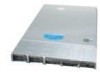
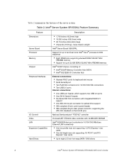
... inch hot-swap SATA / SAS drives 4 Intel® Server System SR1550AL/SR1550ALSAS User's Guide Intel® Server System SR1550AL Feature Summary Feature Dimensions Server Board Processor Memory Chipset Peripheral Interfaces I /O Controller Hub ...External connections: • Stacked PS/2* ports for keyboard and mouse • RJ45 Serial B port • Two RJ45 NIC connectors for 10/100/1000 Mb...
... inch hot-swap SATA / SAS drives 4 Intel® Server System SR1550AL/SR1550ALSAS User's Guide Intel® Server System SR1550AL Feature Summary Feature Dimensions Server Board Processor Memory Chipset Peripheral Interfaces I /O Controller Hub ...External connections: • Stacked PS/2* ports for keyboard and mouse • RJ45 Serial B port • Two RJ45 NIC connectors for 10/100/1000 Mb...

User Guide
Page 25
... Up to two 650W power supply modules • Six 4-pin fan headers supporting two processor fans, and four system fans • Dedicated non-redundant power supply fan (one per module) • One front panel USB port • One internal USB header providing two USB ports Intel® System Management Software Intel® Server System SR1550AL/SR1550ALSAS User's Guide 5
... Up to two 650W power supply modules • Six 4-pin fan headers supporting two processor fans, and four system fans • Dedicated non-redundant power supply fan (one per module) • One front panel USB port • One internal USB header providing two USB ports Intel® System Management Software Intel® Server System SR1550AL/SR1550ALSAS User's Guide 5
User Guide
Page 26
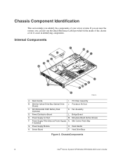
...N. Power Supply Module O. SR1550ALSAS RAID Battery Pack (Optional) K. Power Supply Air Duct M. Server Board P. Rack Handle H. If you are near the system, you identify the components of the chassis cover to assist in identifying components. Bridge Board E.... Reference Label provided on the inside of your server system. Rack Handle I D C B A J K P L M N O TP02212 A. PCI Riser Assembly B. Processor Air Duct C. Mini Control Panel Bay if Installed) G. Hard Drive Bays Figure 2. ChassisComponents 6 Intel® Server System SR1550AL/SR1550ALSAS User's Guide
...N. Power Supply Module O. SR1550ALSAS RAID Battery Pack (Optional) K. Power Supply Air Duct M. Server Board P. Rack Handle H. If you are near the system, you identify the components of the chassis cover to assist in identifying components. Bridge Board E.... Reference Label provided on the inside of your server system. Rack Handle I D C B A J K P L M N O TP02212 A. PCI Riser Assembly B. Processor Air Duct C. Mini Control Panel Bay if Installed) G. Hard Drive Bays Figure 2. ChassisComponents 6 Intel® Server System SR1550AL/SR1550ALSAS User's Guide

User Guide
Page 48
... within the server system. Removing the Processor Air Duct 28 Intel® Server System SR1550AL/SR1550ALSAS User's Guide The air duct is required for instructions on adding or replacing a processor, first remove the processor air duct, and then see "Removing the Chassis Cover". 4. Return to these instructions to reinstall the processor air duct after installing your server server system with the processor air duct...
... within the server system. Removing the Processor Air Duct 28 Intel® Server System SR1550AL/SR1550ALSAS User's Guide The air duct is required for instructions on adding or replacing a processor, first remove the processor air duct, and then see "Removing the Chassis Cover". 4. Return to these instructions to reinstall the processor air duct after installing your server server system with the processor air duct...

User Guide
Page 49
... reveal underside. 5. Plug all peripheral devices and the AC power cable. 3. Installing the Processor Air Duct Intel® Server System SR1550AL/SR1550ALSAS User's Guide 29 Do not remove memory air deflector. TP02227 Figure 22. only if two processors are installed) 6. Place the processor air duct over to pinch or disengage cables that may be near or under...
... reveal underside. 5. Plug all peripheral devices and the AC power cable. 3. Installing the Processor Air Duct Intel® Server System SR1550AL/SR1550ALSAS User's Guide 29 Do not remove memory air deflector. TP02227 Figure 22. only if two processors are installed) 6. Place the processor air duct over to pinch or disengage cables that may be near or under...

User Guide
Page 51
... any parts you install a processor that came with your server chassis for instructions on installing the server's cover. Position the DIMM above the socket. See the documentation that is inserted, push down on the bottom edge of the DIMM until the retaining clips snap into the socket. 10. Intel® Server System SR1550AL/SR1550ALSAS User's Guide 31...
... any parts you install a processor that came with your server chassis for instructions on installing the server's cover. Position the DIMM above the socket. See the documentation that is inserted, push down on the bottom edge of the DIMM until the retaining clips snap into the socket. 10. Intel® Server System SR1550AL/SR1550ALSAS User's Guide 31...

User Guide
Page 52
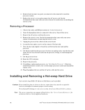
... documentation that came with your server chassis for instructions on the processor and the socket, and insert the processor into the socket. 32 Intel® Server System SR1550AL/SR1550ALSAS User's Guide Line up the alignment marks on removing the server's cover. 5. Installing the Processor To install a processor, follow these instructions: 1. Remove the server's cover. Locate the processor socket and raise the socket...
... documentation that came with your server chassis for instructions on the processor and the socket, and insert the processor into the socket. 32 Intel® Server System SR1550AL/SR1550ALSAS User's Guide Line up the alignment marks on removing the server's cover. 5. Installing the Processor To install a processor, follow these instructions: 1. Remove the server's cover. Locate the processor socket and raise the socket...

User Guide
Page 53
... screws on the bottom of it. Removing the Socket Cover 9. Installing the Heat Sink Intel® Server System SR1550AL/SR1550ALSAS User's Guide 33 Set the heat sink over the processor, lining up the four captive screws with the four posts surrounding the processor. 2. Gradually and equally tighten each captive screw until each is firmly tightened. 3 2 1 4 TP02328...
... screws on the bottom of it. Removing the Socket Cover 9. Installing the Heat Sink Intel® Server System SR1550AL/SR1550ALSAS User's Guide 33 Set the heat sink over the processor, lining up the four captive screws with the four posts surrounding the processor. 2. Gradually and equally tighten each captive screw until each is firmly tightened. 3 2 1 4 TP02328...
User Guide
Page 54
... the four captive screws on the corners of supported hardware. 34 Intel® Server System SR1550AL/SR1550ALSAS User's Guide Do not force the heat sink from the processor. Note: The server system does not support all peripheral devices connected to your server chassis for instructions on installing the server's cover. Twist the heat sink slightly to a list of the...
... the four captive screws on the corners of supported hardware. 34 Intel® Server System SR1550AL/SR1550ALSAS User's Guide Do not force the heat sink from the processor. Note: The server system does not support all peripheral devices connected to your server chassis for instructions on installing the server's cover. Twist the heat sink slightly to a list of the...

User Guide
Page 60
... Bezel". 9. Remove the processor air duct by lifting straight up. 5. If no device will be installed in this location, install a filler blank in cards. 40 Intel® Server System SR1550AL/SR1550ALSAS User's Guide Observe the safety and ESD precautions at the beginning of this location. 7. Install the server system cover. For instructions, see "Installing the Server System Cover". 8. (Optional...
... Bezel". 9. Remove the processor air duct by lifting straight up. 5. If no device will be installed in this location, install a filler blank in cards. 40 Intel® Server System SR1550AL/SR1550ALSAS User's Guide Observe the safety and ESD precautions at the beginning of this location. 7. Install the server system cover. For instructions, see "Installing the Server System Cover". 8. (Optional...

User Guide
Page 62
... instructions, see "Installing the Server System Cover". 7. See your add-in card documentation for information and add-in cards that require them. For instructions, see "Installing the Processor Air Duct". 6. Installing PCI...server system back panel slots. The riser cards will seat into the Server System 3. Press down uniformly until the three hooks on the server board. 4. Re-install the processor air duct. C A B AF000363 Figure 36. Install the server system cover. Plug all peripheral devices and the AC power cable into the server. 42 Intel® Server System SR1550AL...
... instructions, see "Installing the Server System Cover". 7. See your add-in card documentation for information and add-in cards that require them. For instructions, see "Installing the Processor Air Duct". 6. Installing PCI...server system back panel slots. The riser cards will seat into the Server System 3. Press down uniformly until the three hooks on the server board. 4. Re-install the processor air duct. C A B AF000363 Figure 36. Install the server system cover. Plug all peripheral devices and the AC power cable into the server. 42 Intel® Server System SR1550AL...

User Guide
Page 63
..., see letter "C" in cards from the system or wall outlet. Disconnect any cables attached to any add-in the figure below). For instructions, see "Removing the Chassis Cover". 4. Intel® Server System SR1550AL/SR1550ALSAS User's Guide 43 Observe the safety ...and ESD precautions at the end of service, turn off the system by pressing the power button, and unplug the AC power cord from the PCI riser connector. For instructions, see letter "B" in the figure below ). 9. Remove the processor...
..., see letter "C" in cards from the system or wall outlet. Disconnect any cables attached to any add-in the figure below). For instructions, see "Removing the Chassis Cover". 4. Intel® Server System SR1550AL/SR1550ALSAS User's Guide 43 Observe the safety ...and ESD precautions at the end of service, turn off the system by pressing the power button, and unplug the AC power cord from the PCI riser connector. For instructions, see letter "B" in the figure below ). 9. Remove the processor...

User Guide
Page 64
...-install the processor air duct. B A C TP02238 Figure 37. For instructions, see "Installing the PCI-X* Riser Card into the server system. For instructions, see "Installing the Processor Air Duct...Server System 10. See your add-in card documentation for information and add-in card requirements. 14. Install the PCI riser assembly into the Server System". 11. Plug all peripheral devices and the AC power cable into the server. 44 Intel® Server System SR1550AL/SR1550ALSAS User's Guide Install the server system cover. For instructions, see "Installing the Server System...
...-install the processor air duct. B A C TP02238 Figure 37. For instructions, see "Installing the PCI-X* Riser Card into the server system. For instructions, see "Installing the Processor Air Duct...Server System 10. See your add-in card documentation for information and add-in card requirements. 14. Install the PCI riser assembly into the Server System". 11. Plug all peripheral devices and the AC power cable into the server. 44 Intel® Server System SR1550AL/SR1550ALSAS User's Guide Install the server system cover. For instructions, see "Installing the Server System...

User Guide
Page 65
... "Removing the PCI Riser Assembly". 7. Remove the server system cover. Remove the processor air duct. Slide the riser connector to the left of this book. See your add-in card documentation for information and add-in cards from the PCI riser connector. Install the server system cover. Intel® Server System SR1550AL/SR1550ALSAS User's Guide 45 Observe the safety...
... "Removing the PCI Riser Assembly". 7. Remove the server system cover. Remove the processor air duct. Slide the riser connector to the left of this book. See your add-in card documentation for information and add-in cards from the PCI riser connector. Install the server system cover. Intel® Server System SR1550AL/SR1550ALSAS User's Guide 45 Observe the safety...

User Guide
Page 66
... "Removing the Chassis Cover". 4. 17. Power down the server and unplug all empty add-in card slot (see "Removing the Processor Air Duct". 5. For instructions, see "Installing the PCI Riser Assembly". 46 Intel® Server System SR1550AL/SR1550ALSAS User's Guide Installing an Add-In Card TP02240 9. ... "B"). 8. Remove the PCI riser assembly. Plug all peripheral devices and the AC power cable into the server system. Installing a PCI Add-in card. Remove the server system cover. Open the rear retention clip by pushing the blue slide upward and rotating clip to install and ...
... "Removing the Chassis Cover". 4. 17. Power down the server and unplug all empty add-in card slot (see "Removing the Processor Air Duct". 5. For instructions, see "Installing the PCI Riser Assembly". 46 Intel® Server System SR1550AL/SR1550ALSAS User's Guide Installing an Add-In Card TP02240 9. ... "B"). 8. Remove the PCI riser assembly. Plug all peripheral devices and the AC power cable into the server system. Installing a PCI Add-in card. Remove the server system cover. Open the rear retention clip by pushing the blue slide upward and rotating clip to install and ...

User Guide
Page 67
.... Removing a PCI Add-in card slots have filler panels installed. 9. Remove the server system cover. Remove the processor air duct. A B Figure 40. Remove the PCI add-in card from the riser card connector (see "Installing the Processor Air Duct". 11. Intel® Server System SR1550AL/SR1550ALSAS User's Guide 47 For instructions, see letter "B"). 11. Observe the safety and...
.... Removing a PCI Add-in card slots have filler panels installed. 9. Remove the server system cover. Remove the processor air duct. A B Figure 40. Remove the PCI add-in card from the riser card connector (see "Installing the Processor Air Duct". 11. Intel® Server System SR1550AL/SR1550ALSAS User's Guide 47 For instructions, see letter "B"). 11. Observe the safety and...

User Guide
Page 68
... the Chassis Cover". 4. Squeeze the sides of this book. Install the processor air duct. For instructions, see "Installing the PCI Riser Assembly". 8. For instructions, see "Installing the Processor Air Duct". 48 Intel® Server System SR1550AL/SR1550ALSAS User's Guide 12. Attach the standoffs to the server board (see letter "C" in the figure below) and attach the I/O expansion...
... the Chassis Cover". 4. Squeeze the sides of this book. Install the processor air duct. For instructions, see "Installing the PCI Riser Assembly". 8. For instructions, see "Installing the Processor Air Duct". 48 Intel® Server System SR1550AL/SR1550ALSAS User's Guide 12. Attach the standoffs to the server board (see letter "C" in the figure below) and attach the I/O expansion...

User Guide
Page 69
... Server System Cover". 11. Remove the standoffs from the server board (see letter "B" in the figure below ). 6. B A C AF000749 Figure 42. Install the PCI riser assembly into the server. Observe the safety and ESD precautions at the beginning of this book. For instructions, see "Removing the Chassis Cover". 4. 9. Intel® Server System SR1550AL/SR1550ALSAS User's Guide 49 Install the processor...
... Server System Cover". 11. Remove the standoffs from the server board (see letter "B" in the figure below ). 6. B A C AF000749 Figure 42. Install the PCI riser assembly into the server. Observe the safety and ESD precautions at the beginning of this book. For instructions, see "Removing the Chassis Cover". 4. 9. Intel® Server System SR1550AL/SR1550ALSAS User's Guide 49 Install the processor...